Install the retimer assembly
Follow instructions in this section to install the retimer assembly.
About this task
Read Installation Guidelines and Safety inspection checklist to ensure that you work safely.
Touch the static-protective package that contains the component to any unpainted metal surface on the server; then, remove it from the package and place it on a static-protective surface.
Procedure
- Adjust the SXM GPU board.
 Pull out the SXM GPU board latch outward until it stops.
 Rotate down the clips and handle so that they are away from the retimer assembly guide pins.Figure 1. Adjusting the SXM GPU board
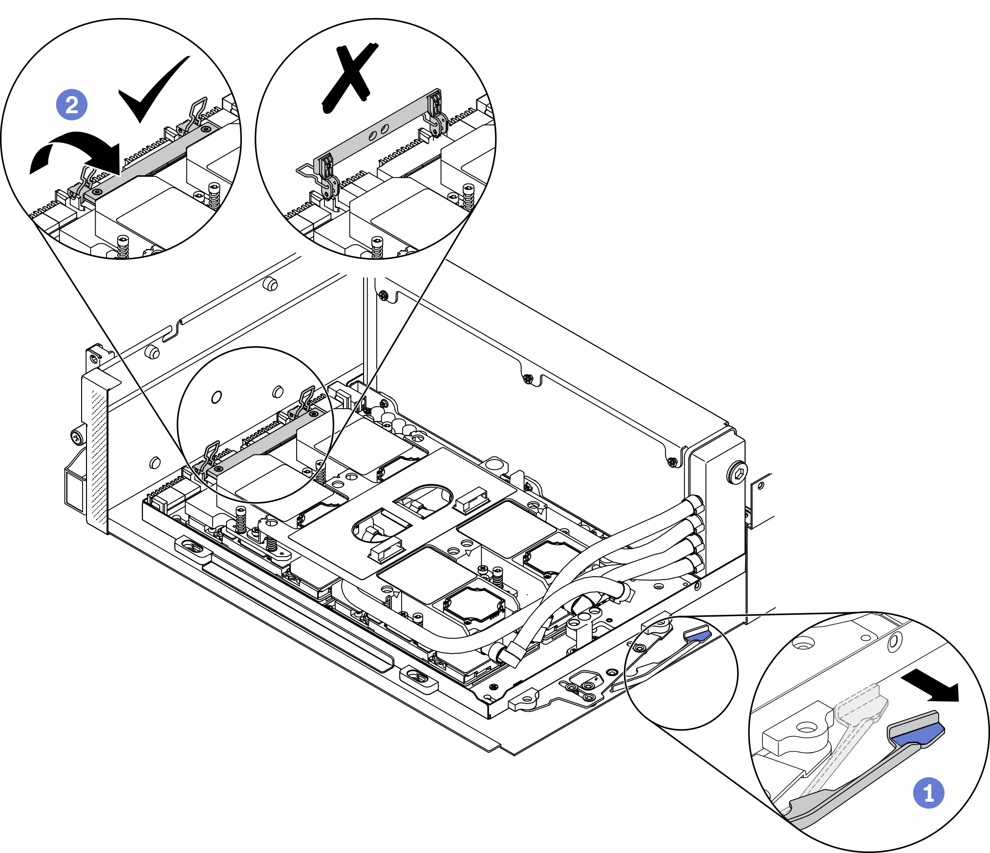
- Align the retimer assembly with the four guide pins; then, attach the retimer assembly to the chassis, and slide it down to secure it in place.AttentionKeep the
SXM GPU board clips and handle away from the retimer assembly to prevent damages to the retimer assembly. Figure 2. Installing the retimer assembly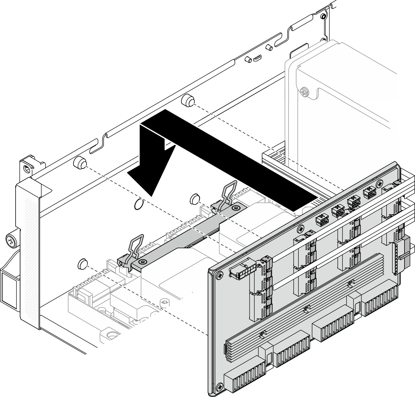
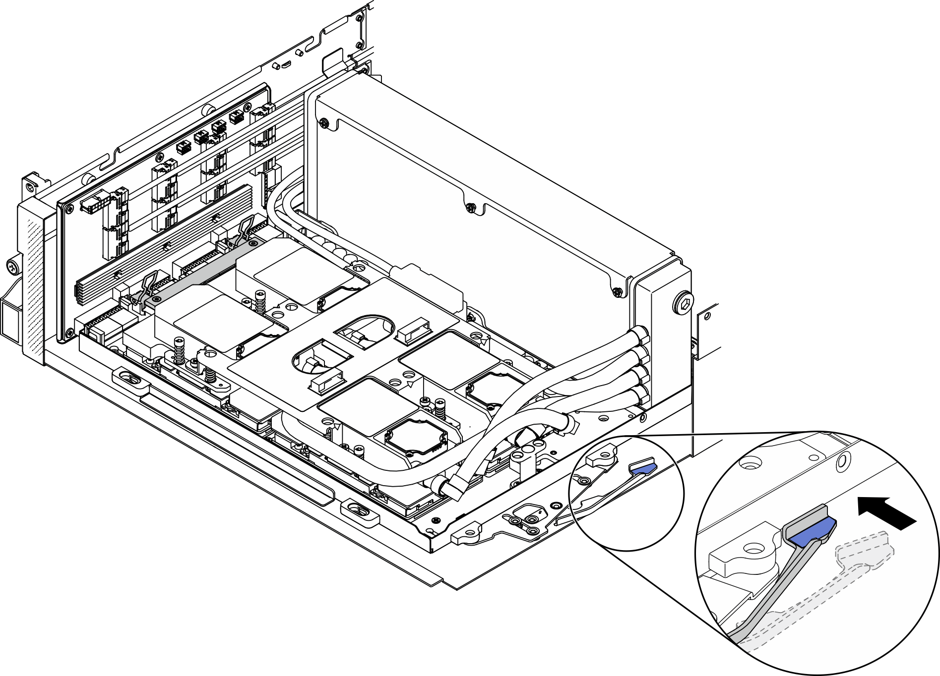
- Pull the SXM GPU board latch inward to connect the SXM GPU board to the retimer assembly.Figure 3. Connecting SXM GPU board to the retimer assembly
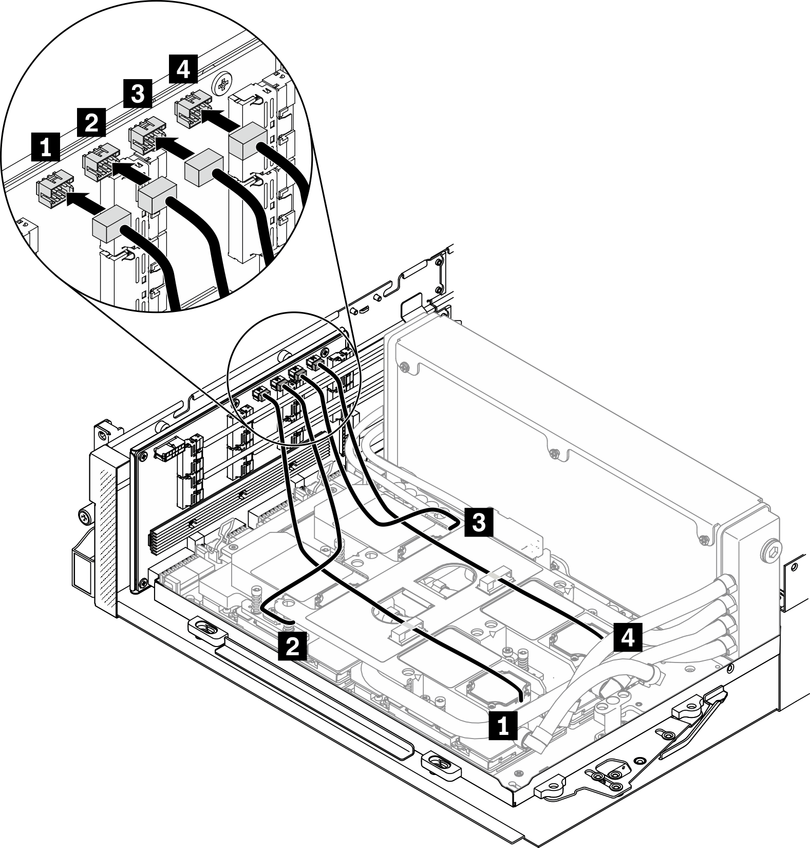
- Connect the four cold plate assembly pump cables to the retimer assembly.Figure 4. Connecting cold plate assembly pump cables to the retimer assembly
- Route the retimer assembly power cable through the cable clips, and connect the power cable to the retimer assembly and the system board.Figure 5. Connecting the retimer assembly power cable
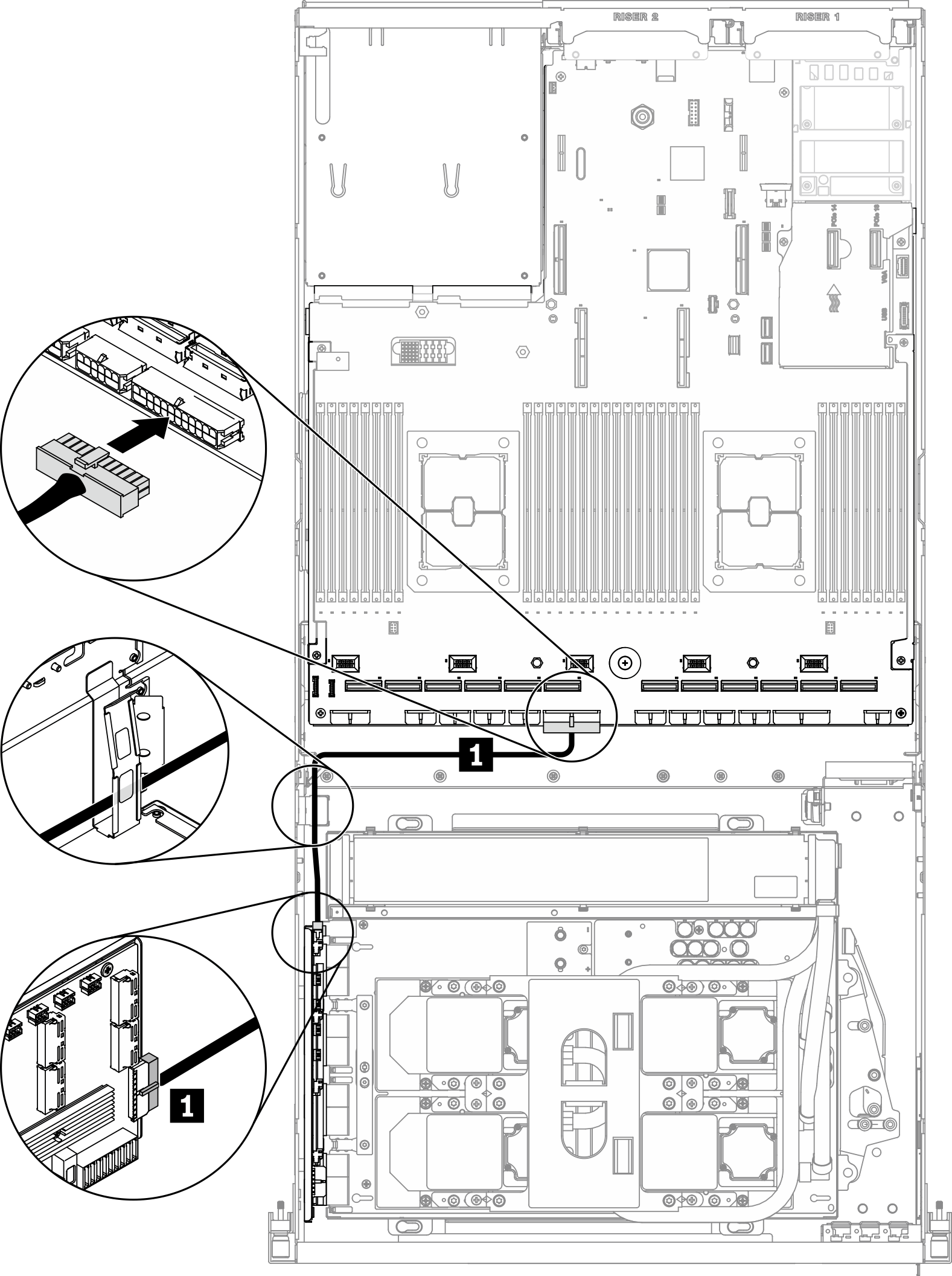
1 Retimer power cable From To Retimer Power connector System board PCIe adapter distribution board power 2 connector For detailed information, see System-board connectors.
- Route the eight retimer assembly signal cables through the cable clips, and connect the signal cables to the retimer assembly and the system board.Figure 6. Connecting retimer assembly signal cables
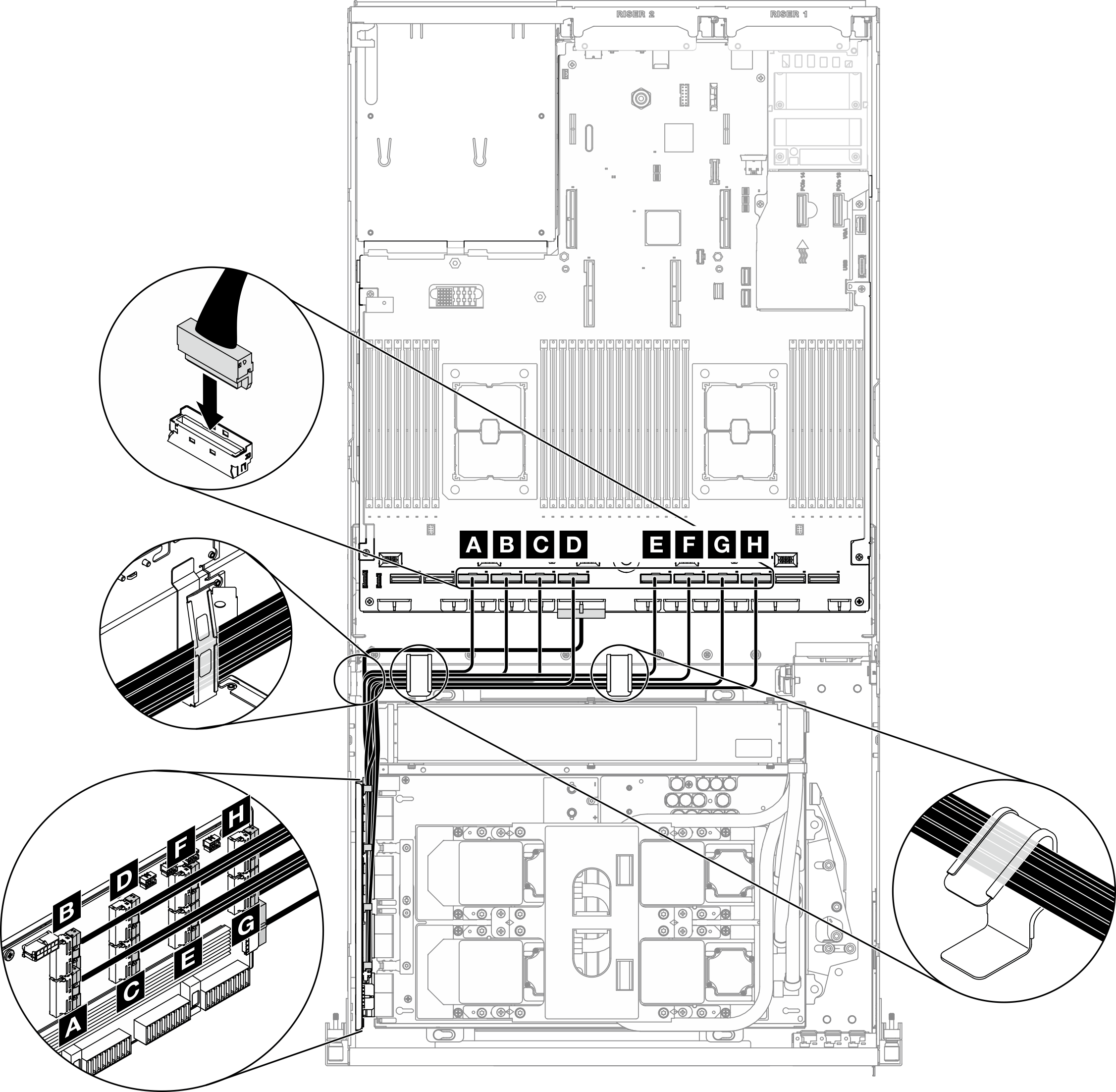
From To Retimer MCIO connector A System board PCIe connector 10 MCIO connector B PCIe connector 9 MCIO connector C PCIe connector 8 MCIO connector D PCIe connector 7 MCIO connector E PCIe connector 6 MCIO connector F PCIe connector 5 MCIO connector G PCIe connector 4 MCIO connector H PCIe connector 3 For detailed information, see System-board connectors.
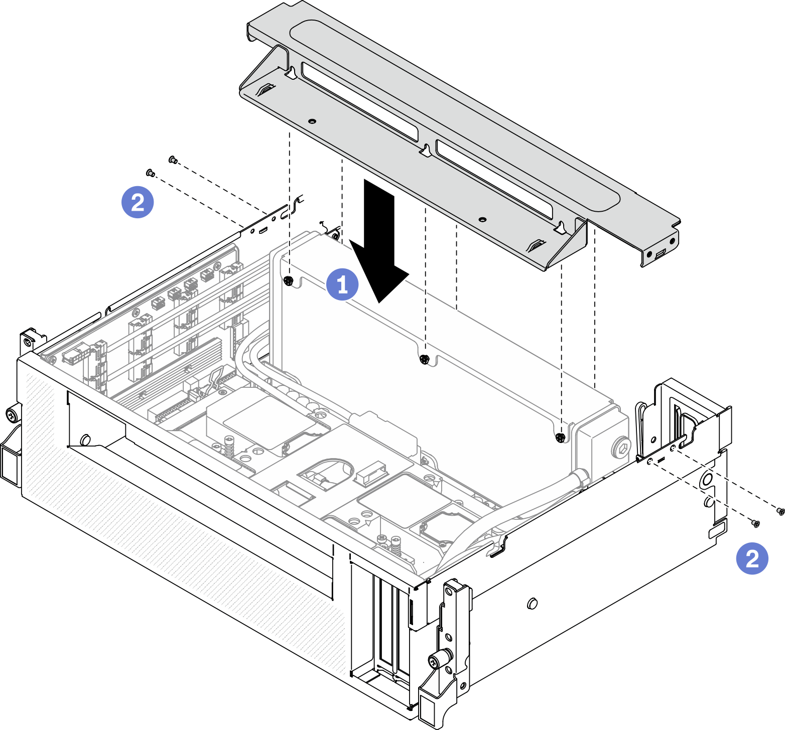
- Install the cross bar.
- Place the cross bar on top of the radiator.
- Fasten the four screws to secure the cross bar to the chassis.Figure 7. Installing the cross bar
After you finish
Reinstall the fan cage. See Install the fan cage.
Reinstall the front I/O expansion board module. See Install the front I/O expansion board module.
Reinstall the network adapter. See Install a network adapter.
Reinstall the 2.5-inch drive cage assembly. See Install the 2.5-inch drive cage assembly.
Complete the parts replacement. See Complete the parts replacement.
Demo video