Install the Lenovo Neptune(TM) liquid-to-air (L2A) hybrid cooling module
Follow instructions in this section to install the Lenovo Neptune® liquid-to-air (L2A) hybrid cooling module.
About this task
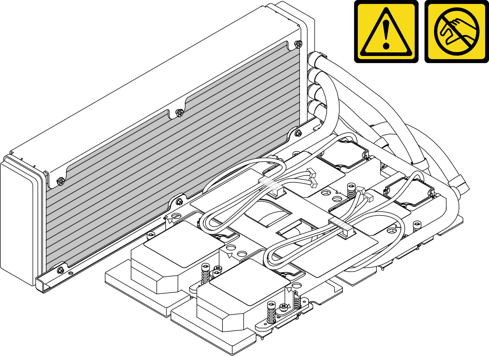
Removing and installing this component requires trained technicians. Do not attempt to remove or install it without proper training.
Read Installation Guidelines and Safety inspection checklist to ensure that you work safely.
| Torque screwdriver type list | Screw Type |
|---|---|
| Phillips #1 head screwdriver | Phillips #1 |
| Torx T10 head screwdriver | Torx T10 screw |
Procedure
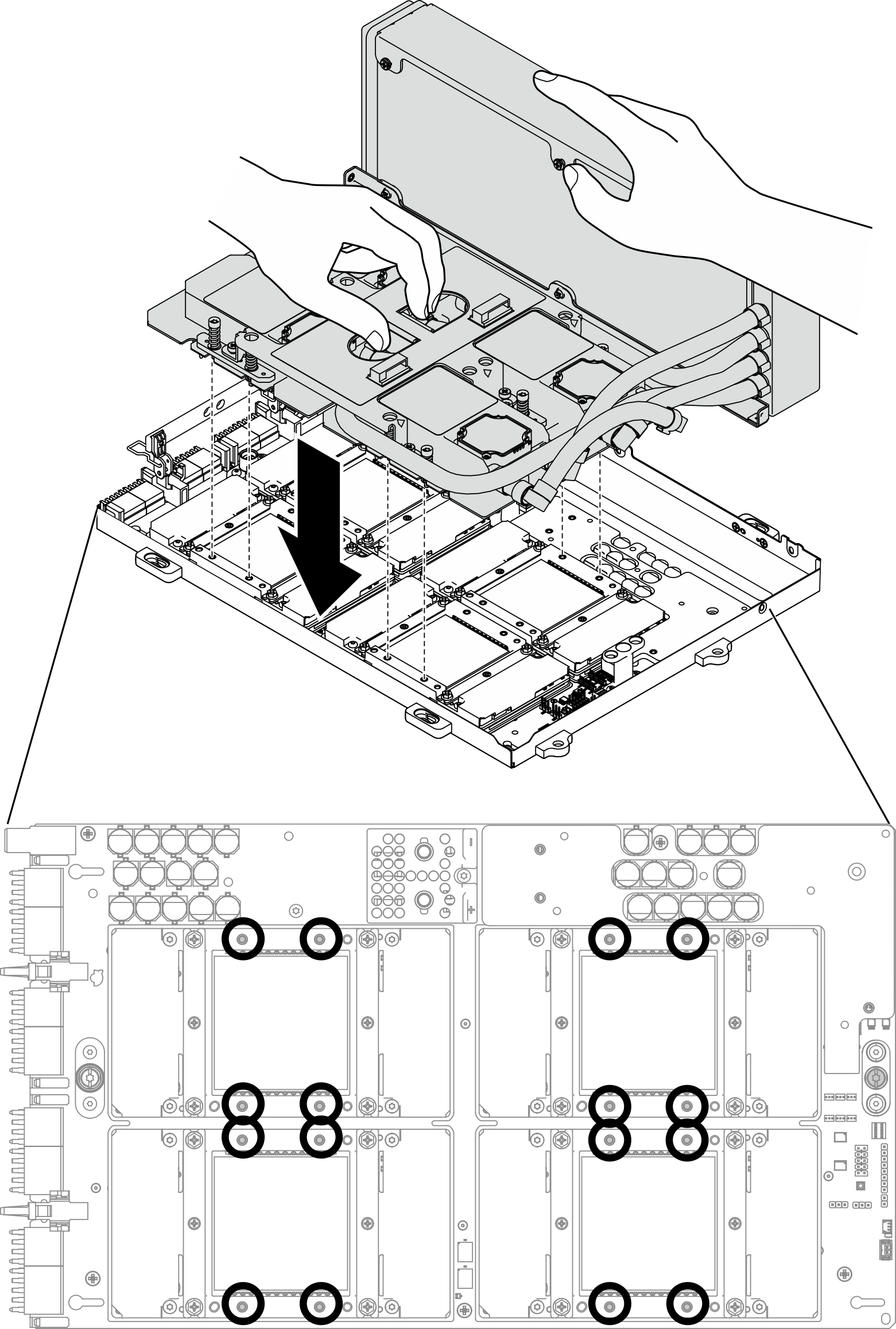
- Align the L2A with the upper left corner of the GPU tray and the screw holes on the SXM GPU board; then, gently place the L2A down onto the SXM GPU board.Figure 1. Placing the L2A onto the SXM GPU board
- With a PH 1 head screwdriver, fasten the seven Philip #1 screws that secure the radiator to the GPU tray. Install the screws with a torque screwdriver set to the proper torque. For reference, the torque required for the screws to fully tighten is 0.3±0.03 newton-meter, 2.7±0.27 pound-inch.Figure 2. Fastening screws to the radiator
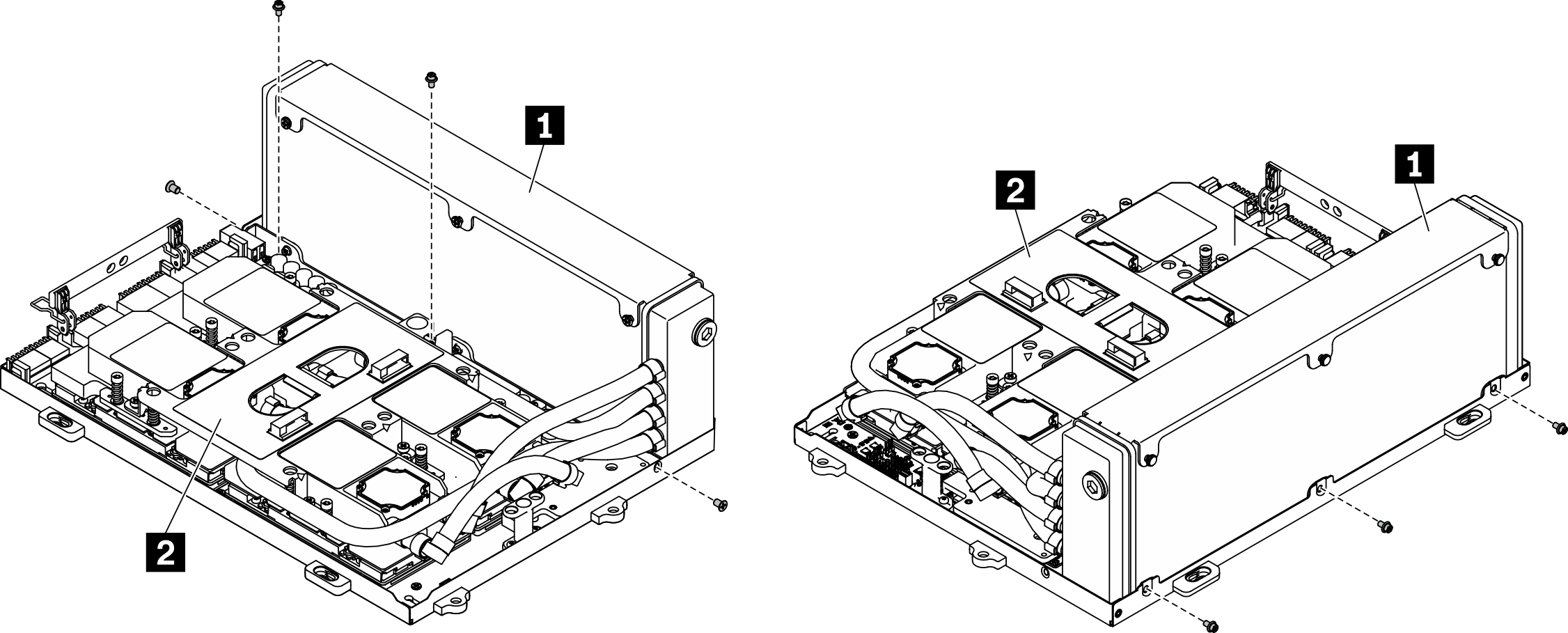
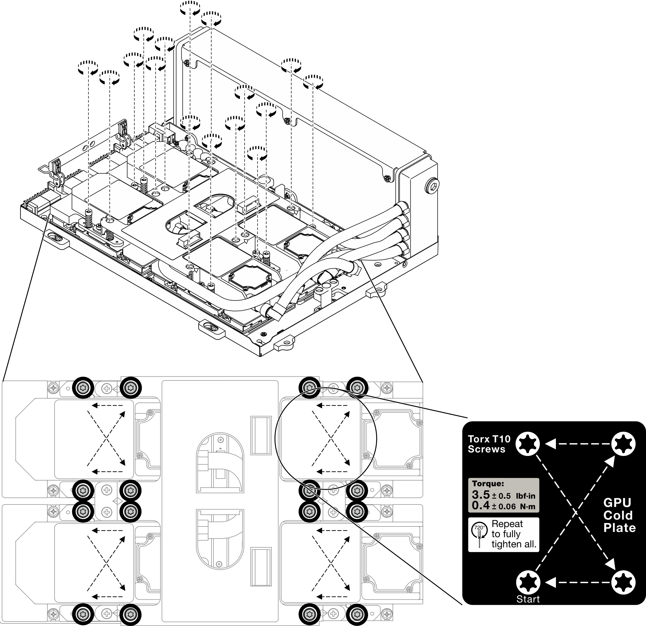
1 Radiator 2 Cold plate assembly - With a Torx 10 screwdriver, fasten the captive screws that secure the cold plates to the SXM GPU board in the installation sequence shown on the cold plate label. Install the screws with a torque screwdriver set to the proper torque. For reference, the torque required for the screws to fully tighten is 0.4±0.06 newton-meter, 3.5±0.5 pound-inch.AttentionTo prevent damage to components, make sure to follow the indicated screw fastening sequence shown on the cold plate label.Figure 3. Fastening screws on the cold plates
- Install the GPU-L2A assembly.
 Pull the GPU-L2A assembly latch outward until it stops.
 Rotate up the clips and handle of the SXM GPU board, and hold the handles on both sides of the SXM GPU board.
 Align the GPU-L2A assembly with the six guide pins in the chassis, and gently place the GPU-L2A assembly into the chassis.Figure 4. Install the GPU-L2A assembly
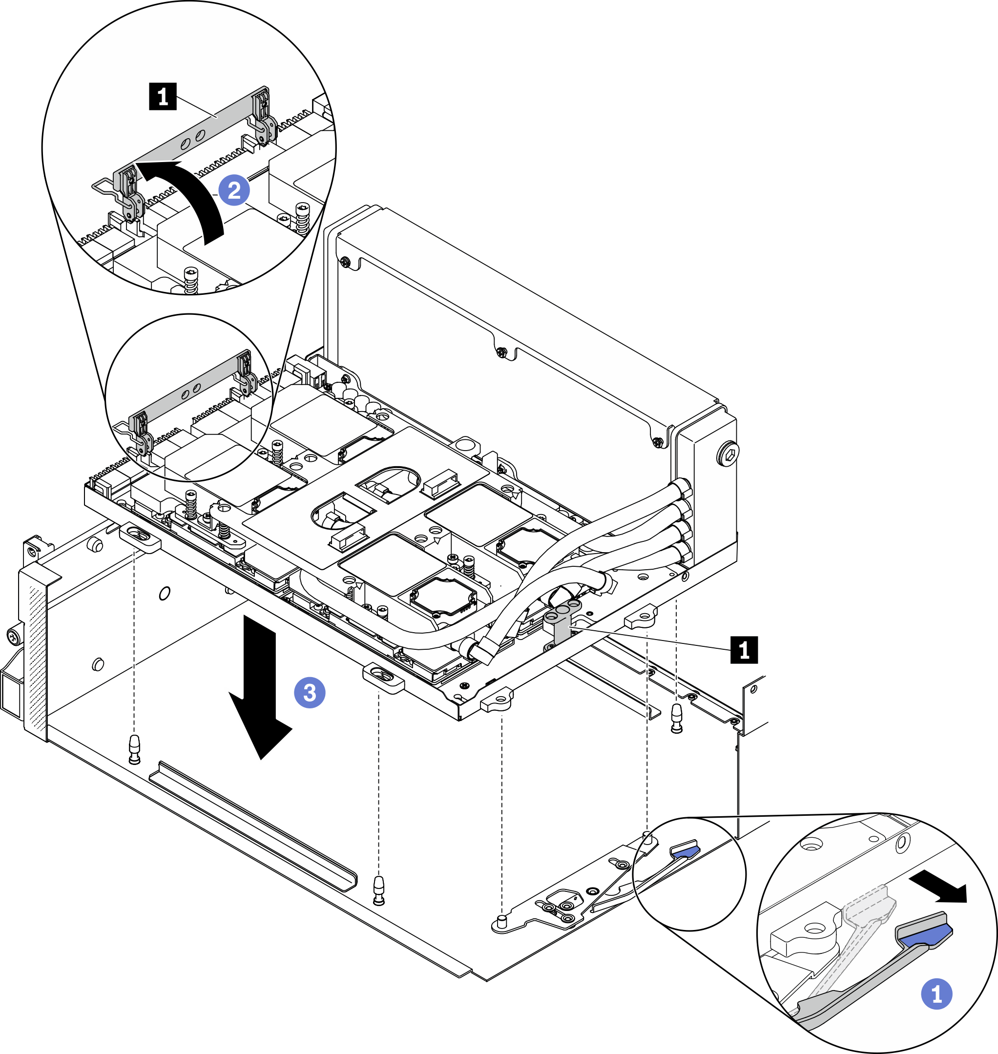
1 SXM GPU board handle
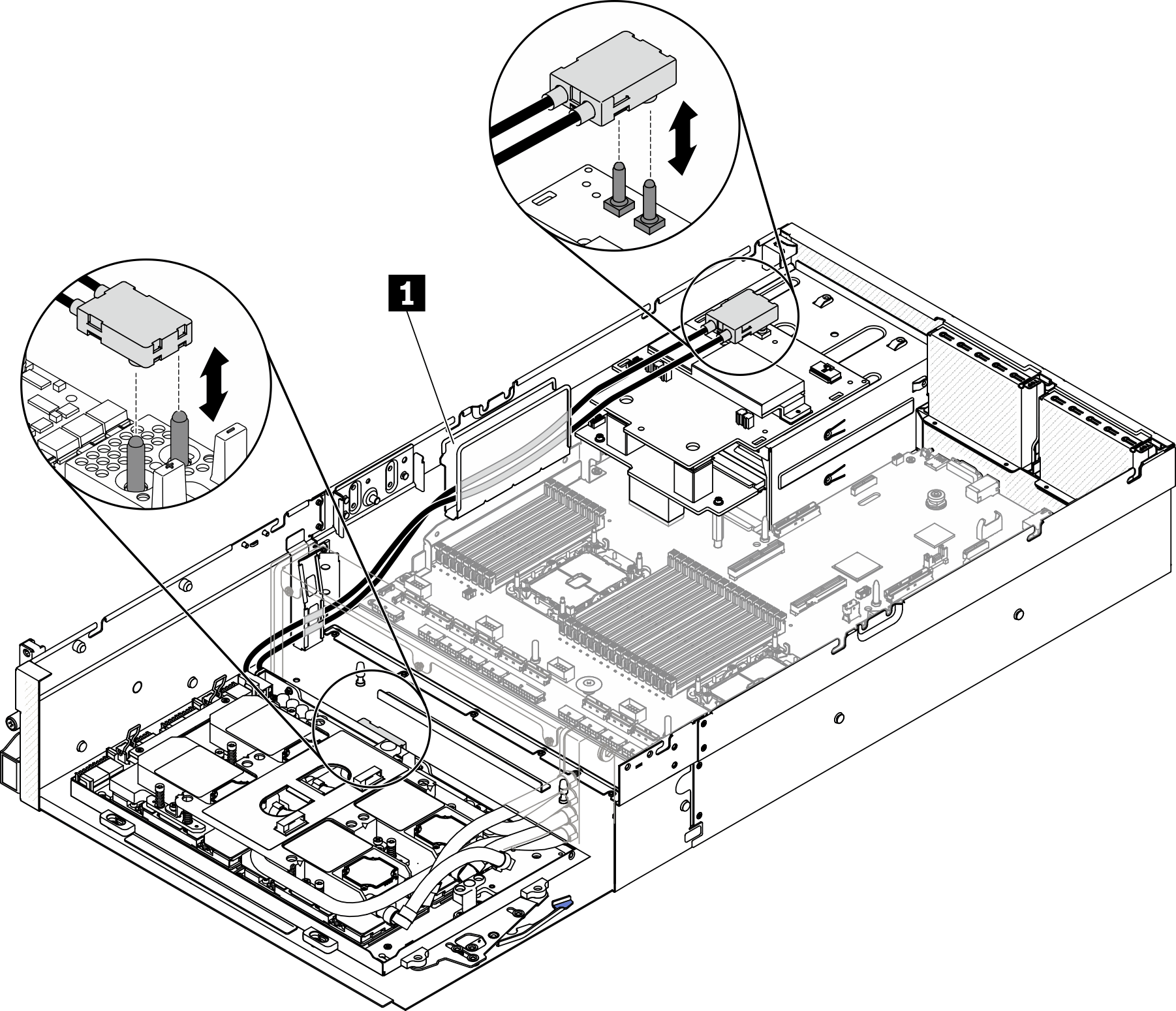
- Route the SXM GPU board power cable through the cable clip and cable guide, and connect it to the SXM GPU board and the SXM GPU power distribution board in the rear of the chassis.AttentionMake sure to route the cables through the cable clip and cable guide.Figure 5. Connecting SXM GPU board power cable
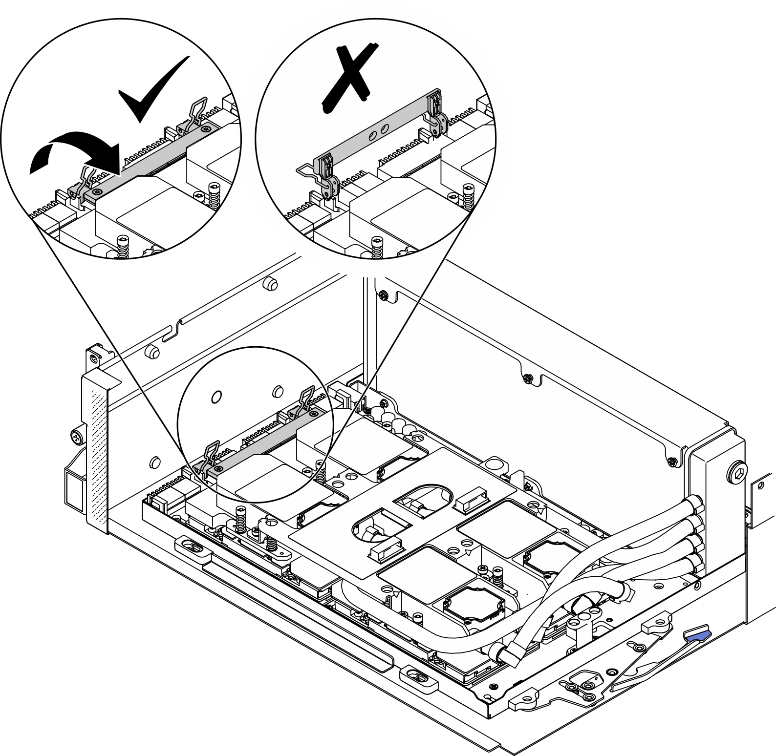
- Rotate down the clips and handle of the SXM GPU board.Figure 6. Rotate down the clips and handle of the SXM GPU board
After you finish
Reinstall the retimer assembly. See Install the retimer assembly.
Reinstall the front I/O expansion board module. See Install the front I/O expansion board module.
Reinstall the network adapter. Install a network adapter.
Reinstall the 2.5-inch drive cage assembly. See Install the 2.5-inch drive cage assembly.
Complete the parts replacement. See Complete the parts replacement.
Demo video