System board components
The illustration in this section shows the component locations on the system board.
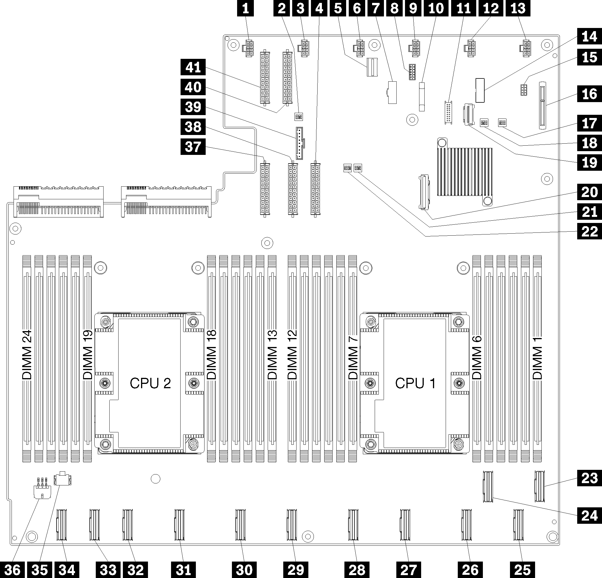
Figure 1. System board components
| Callout | Callout |
|---|---|
| 1 System fan 6 connector | 2 Switch block 1 |
| 3 System fan 5 connector | 4 Power connector 1 |
| 5 XClarity Controller management connector | 6 System fan 4 connector |
| 7 Front panel VGA connector | 8 Serial connector |
| 9 System fan 3 connector | 10 3V battery (CR2032) |
| 11 Front panel USB connector | 12 System fan 2 connector |
| 13 System fan 1 connector | 14 TPM header |
| 15 Storage management connector | 16 M.2 backplane connector |
| 17 PCH/ME switch block | 18 Switch block 3 |
| 19 PCIe connector 13 (PCIe x4) | 20 SATA connector |
| 21 FPGA switch block | 22 Switch block 2 |
| 23 PCIe connector 1 (CPU1) | 24 PCIe connector 2 (CPU1) |
| 25 PCIe connector 3 (CPU1) | 26 PCIe connector 4 (CPU1) |
| 27 PCIe connector 5 (CPU1) | 28 PCIe connector 6 (CPU1) |
| 29 PCIe connector 7 (CPU2) | 30 PCIe connector 8 (CPU2) |
| 31 PCIe connector 9 (CPU2) | 32 PCIe connector 10 (CPU2) |
| 33 PCIe connector 11 (CPU2) | 34 PCIe connector 12 (CPU2) |
| 35 I/O cage power connector 2 | 36 I/O cage power connector 1 |
| 37 Power connector 5 | 38 Power connector 2 |
| 39 Operator panel connector | 40 Power connector 3 |
| 41 Power connector 4 |
The system board is secured by two air baffle posts, two M.2 adapter guideposts, and 10 screws. See the following image for the locations.
Figure 2. System board screw locations
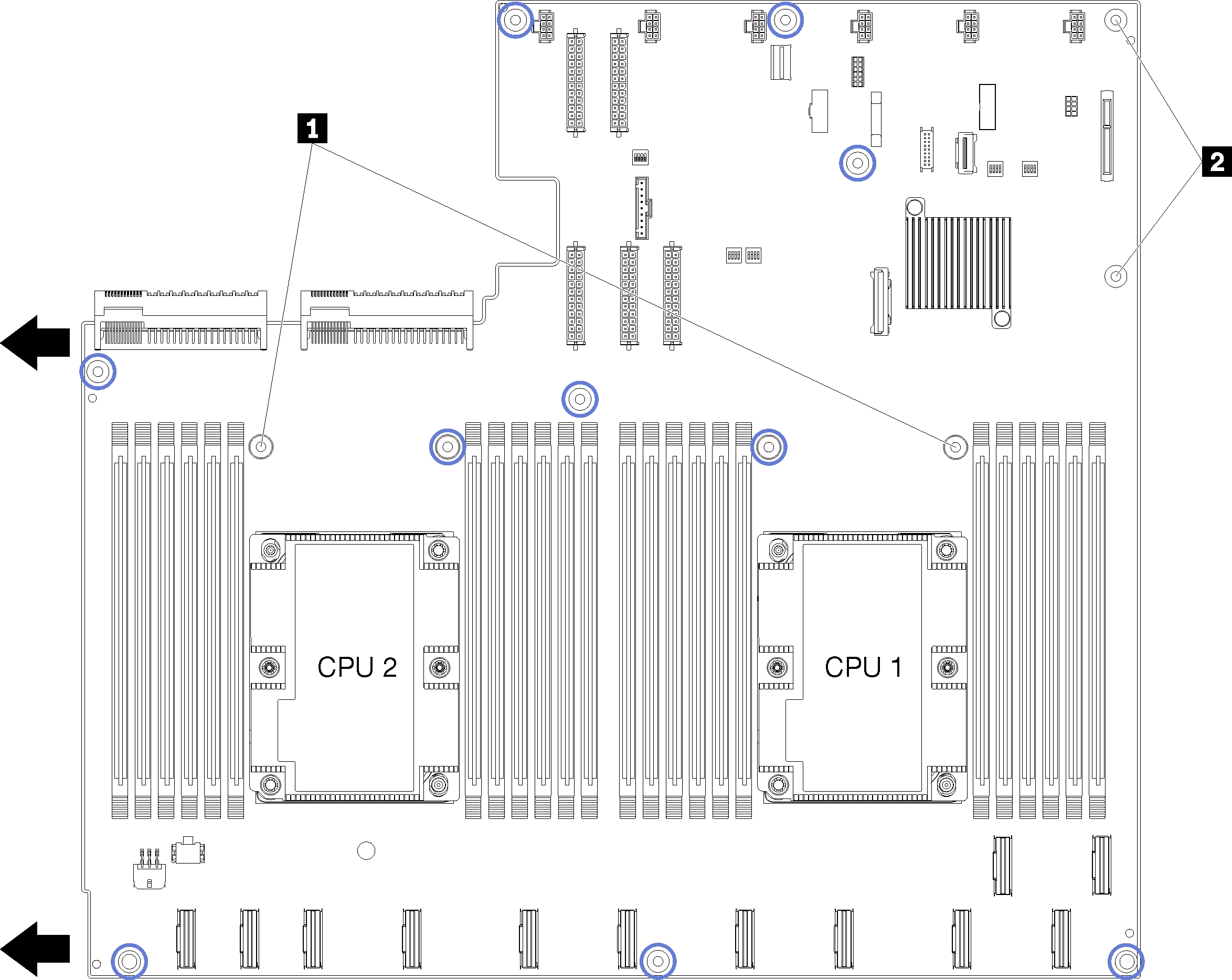
| 1 Air baffle posts |
| 2 M.2 adapter guideposts |
Give documentation feedback