Install the chassis to rack
Follow instructions in this section to install the chassis to the rack. The procedure must be executed by a trained technician.
S036
 |  |
| 18 - 32 kg (39 - 70 lb) | 32 - 55 kg (70 - 121 lb) |
CAUTION
Use safe practices when lifting.
S037
CAUTION
The weight of this part or unit is more than 55 kg (121.2 lb). It takes specially trained persons, a lifting device, or both to safely lift this part or unit.
R006
CAUTION
Do not place any object on top of a rack-mounted device unless that rack-mounted device is intended for use as a shelf.
About this task
Attention
Read Installation Guidelines and Safety inspection checklist to ensure that you work safely.
Power off the server and peripheral devices and disconnect the power cords and all external cables. See Power off the server.
- Firmware and driver download: You might need to update the firmware or driver after replacing a component.
Go to Drivers and Software download website for ThinkSystem SR680a V3 to see the latest firmware and driver updates for your server.
Go to Update the firmware for more information on firmware updating tools.
- To install the rails into a rack, follow the instructions that are provided in the Rail installation Guide.
- Two people and one lifting device on site that can support up to 400 lb (181 kg) are required to perform this procedure. If you do not already have a lifting device available, Lenovo offers the Genie Lift GL-8 material lift that can be purchased at Data Center Solution Configurator. Make sure to include the Foot-release brake and the Load Platform when ordering the Genie Lift GL-8 material lift.
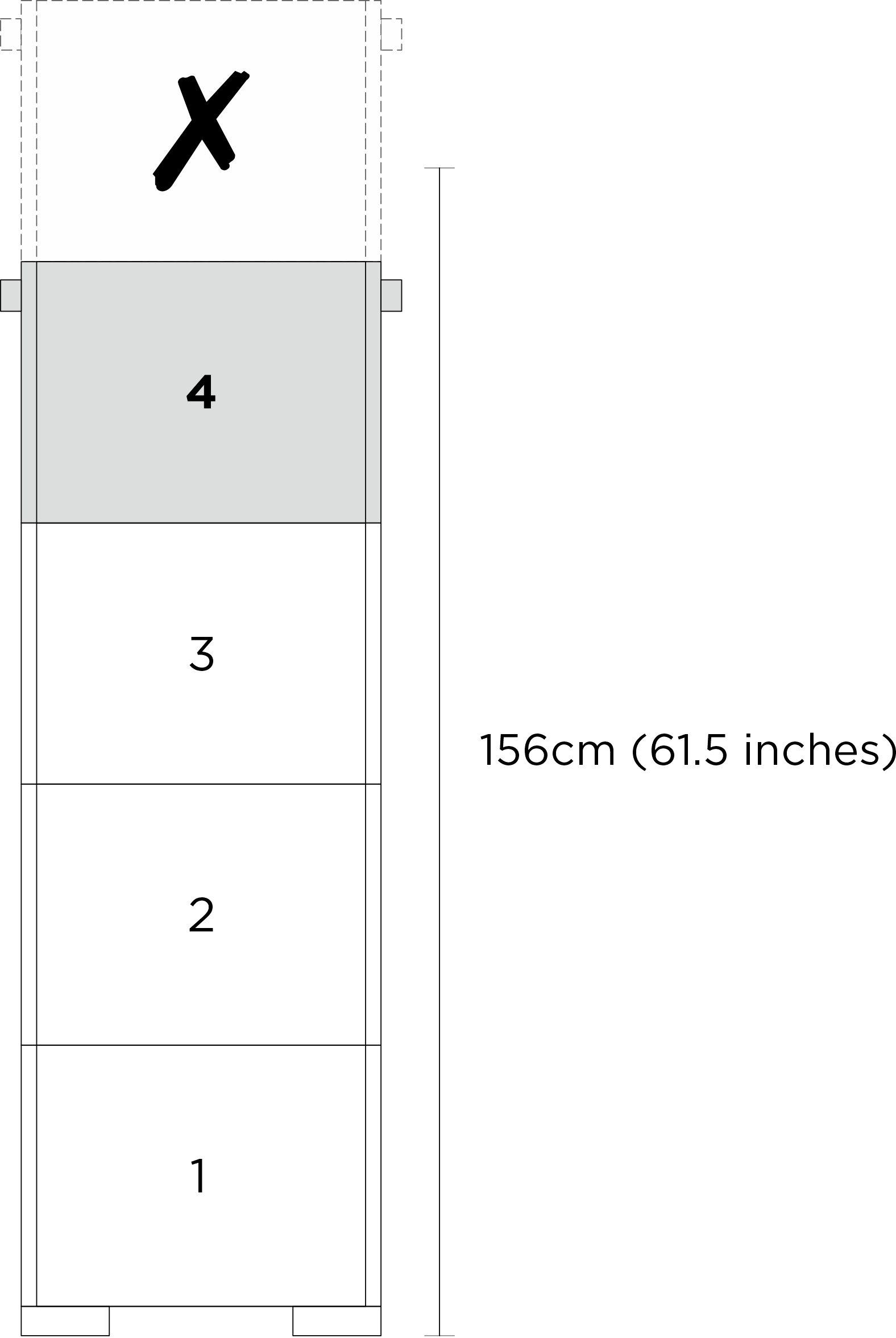
- It is recommended to limit the lift height to a maximum of 156 cm (61.5 inches) during installation. For optimal setup, install up to a maximum of four units per rack, starting from the bottom to the top as illustrated.Figure 1. Recommended maximum installation height
After rails are installed successfully, complete the following steps to install the chassis in a rack.
Procedure
- Attach four handles to the chassis.Figure 2. Attaching four handles
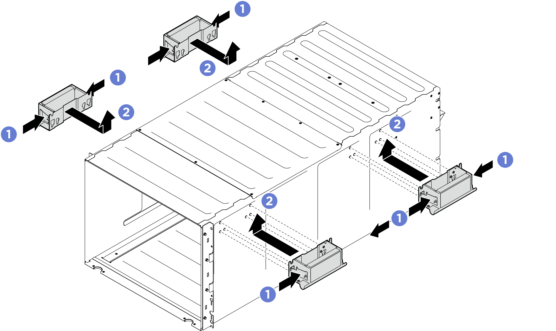
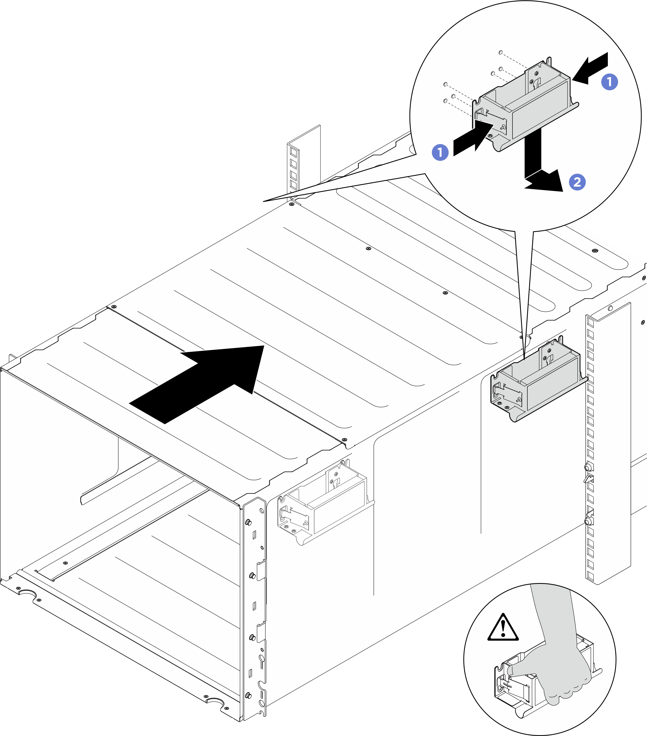
- Carefully put the chassis into the rack with the rear of chassis resting on the rails. Continue to slide the chassis until rear handles are near front rack rails; then, remove rear handles at both sides.Figure 3. Rear handle removal
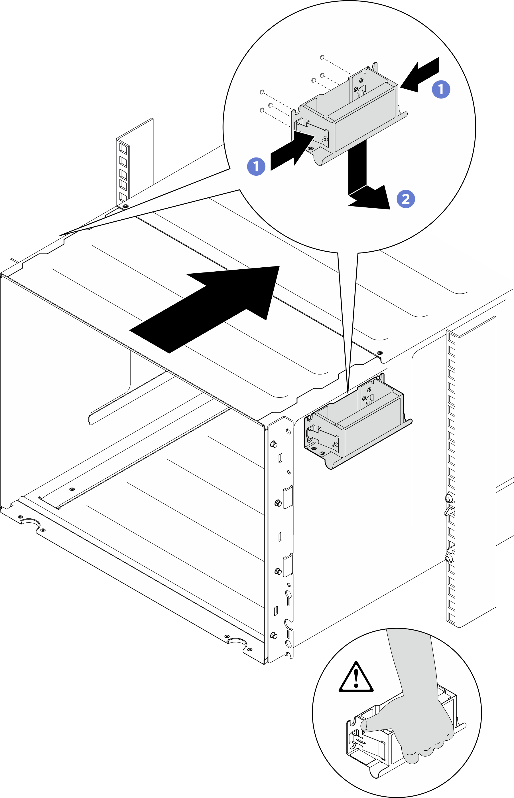
- Slide the chassis farther into the rack until front handles are near front rack rails; then, remove front handles at both sides.Figure 4. Front handle removal
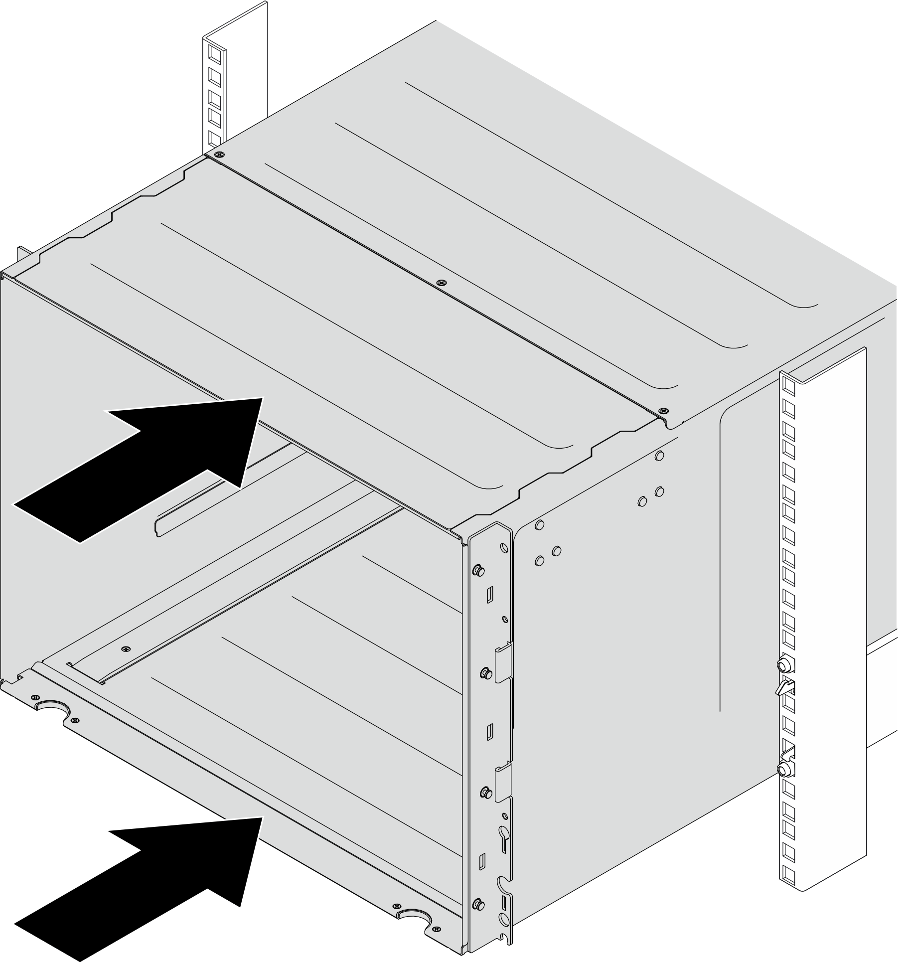
- Slide the chassis all the way back to the rack.Figure 5. Sliding the chassis
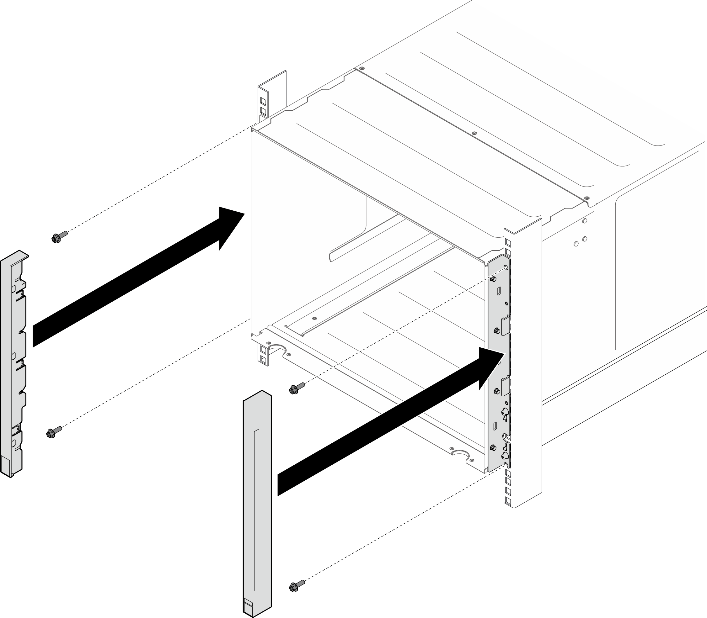
- Secure the chassis to the rack with four screws; then, reinstall the EIA covers.Figure 6. EIA cover installation
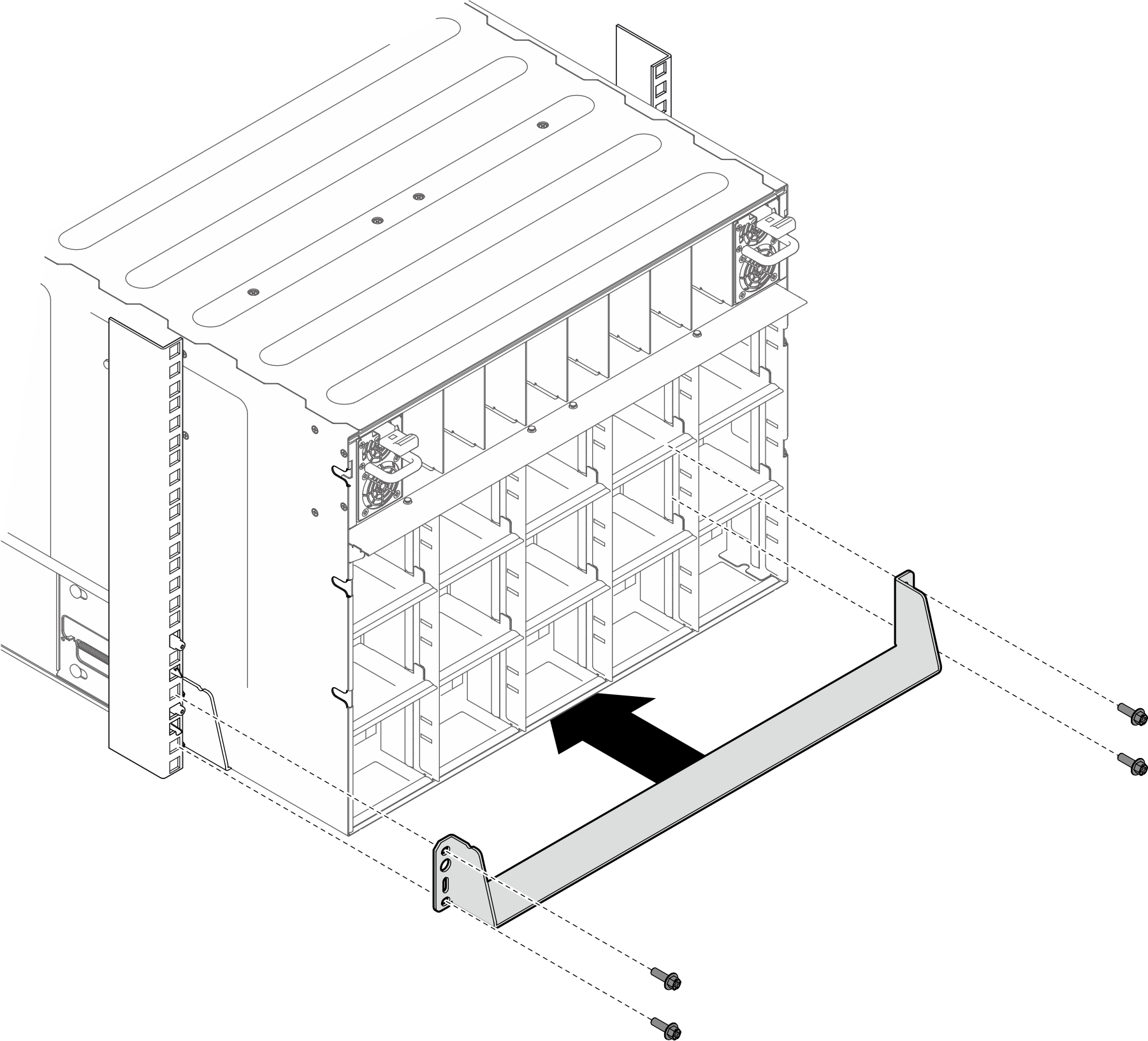
- Secure the lower support bracket on the rear side of the chassis with four screws.Figure 7. Lower support bracket installation
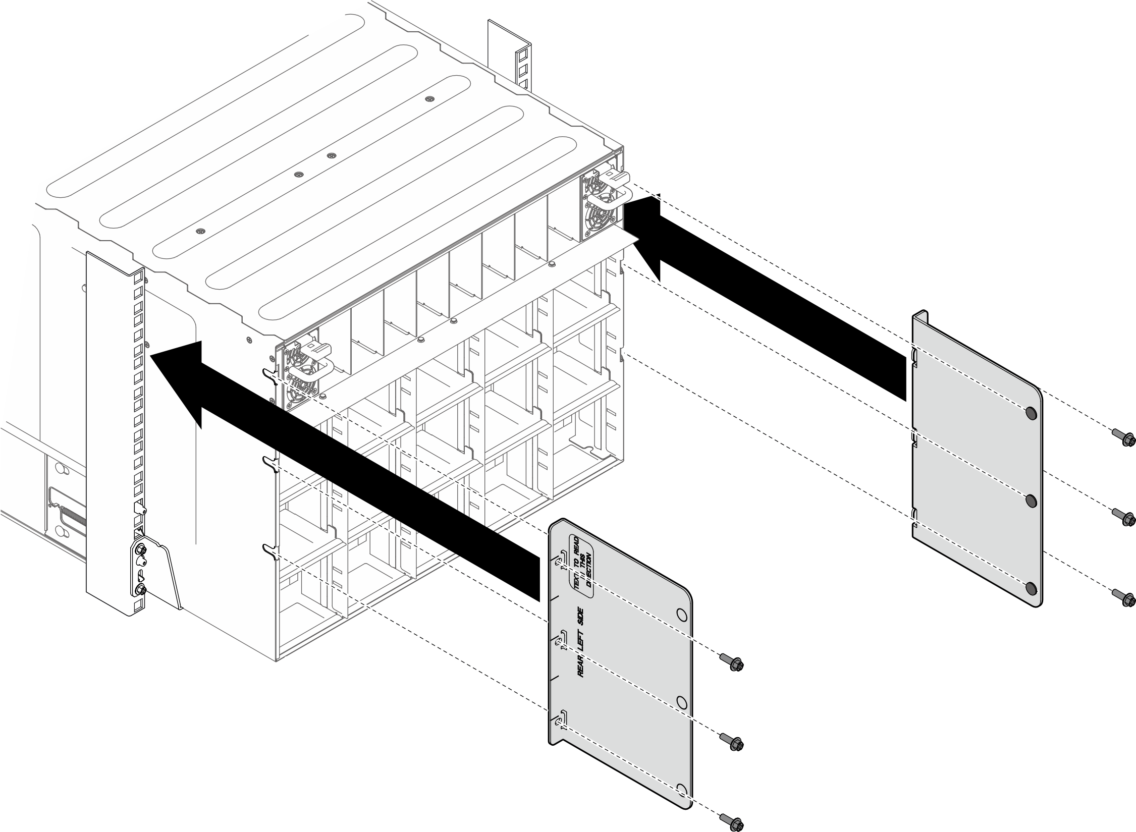
- Secure the two upper support brackets on the rear side of the chassis with six screws.Figure 8. Upper support bracket installation
After you finish
- Reinstall the rear fans. See Install a hot-swap fan.
- Reinstall all the power supply units. See Install a hot-swap power supply unit.
- Reinstall the system shuttle. See Install the system shuttle.
- Install any other required components.
- Reconnect the power cords and any cables that you removed.ImportantFor any AI rack server that supports up to eight CFF PSUs in the rear of the server and operates with N+N redundancy, the two rack-level AC lines feeds must alternate between the PSUs to ensure balanced power distribution and redundancy.
- Rack-level AC line feed A: Connect to PSU 1, 3, 5, 7 (odd numbered PSUs)
- Rack-level AC line feed B: Connect to PSU 2, 4, 6, 8 (even numbered PSUs)
- Power on the server and any peripheral devices. See Power on the server.
- Update the server configuration. See Complete the parts replacement.
Give documentation feedback