Install the cable holder frame and baffle assembly
Follow instructions in this section to install the cable holder frame and baffle assembly. The procedure must be executed by a trained technician.
About this task
Attention
- Read Installation Guidelines and Safety inspection checklist to ensure that you work safely.
- Touch the static-protective package that contains the component to any unpainted metal surface on the server; then, remove it from the package and place it on a static-protective surface.
- Two people and one lifting device on site that can support up to 400 lb (181 kg) are required to perform this procedure. If you do not already have a lifting device available, Lenovo offers the Genie Lift GL-8 material lift that can be purchased at Data Center Solution Configurator. Make sure to include the Foot-release brake and the Load Platform when ordering the Genie Lift GL-8 material lift.
Procedure
- Install the cable holder frame and baffle assembly.
 Align the assembly with the guide pins on the 8U GPU shuttle; then, place the assembly into the 8U GPU shuttle until it is securely engaged.
 Locate the eight screw holes marked with J on the assembly and both sides of the 8U GPU shuttle; then, fasten the eight screws to secure the assembly.Figure 1. Cable holder frame and baffle assembly installation
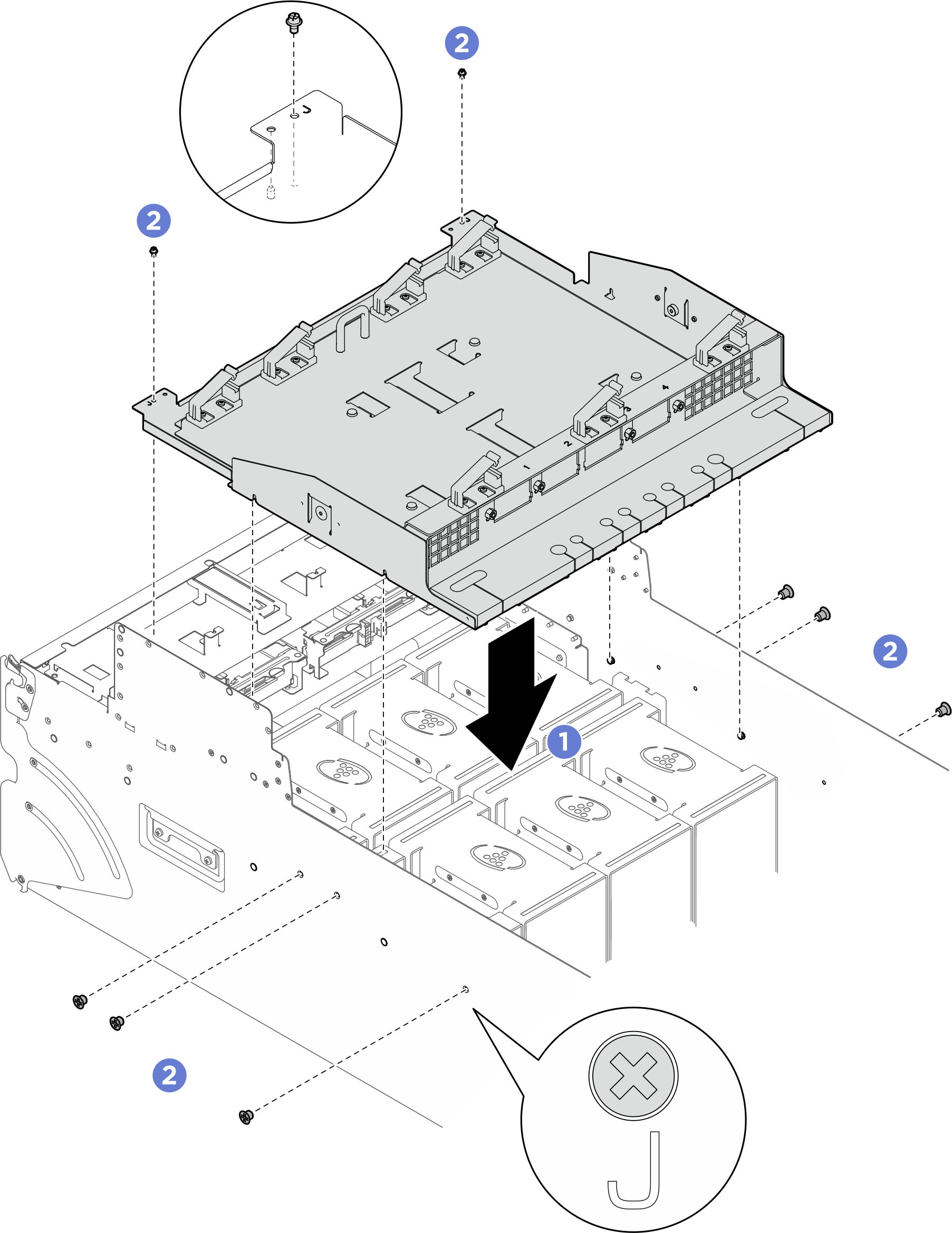
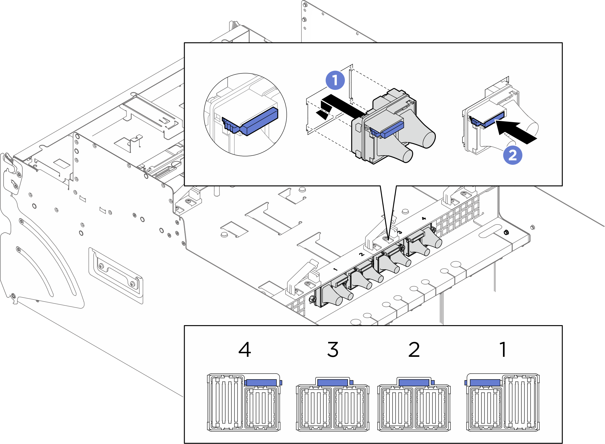
- Install the cables to the cable holder frame and baffle assembly.NoteMake sure to install the cables with correct orientations, see the illustration below for corresponding orientations.
- Align the cable with the port frame, and lower it to install it to the assembly.
- Slide the blue latch to lock the cable into place.Figure 2. Cable installation
After you finish
- Reinstall the PCIe switch tray. See Install the PCIe switch tray.
- Reinstall the front PCIe switch cable harness. See Install the front PCIe switch cable harness.
- Reinstall the integrated diagnostics panel. See Install the integrated diagnostics panel.
- Reinstall the front fan cage. See Install the front fan cage.
- Reinstall the I/O cover. See Install the I/O cover.
- Reinstall the cable cover. See Install the cable cover.
- Reinstall the 8U GPU shuttle. See Install the 8U GPU shuttle.
- Reinstall all the 2.5-inch hot-swap drives or drive bay fillers (if any) into the drive bays. See Install a 2.5-inch hot-swap drive
- Reinstall all the front fans. See Install a front hot-swap fan.
- Reinstall all the power supply units. See Install a hot-swap power supply unit.
- Complete the parts replacement. See Complete the parts replacement.
Give documentation feedback