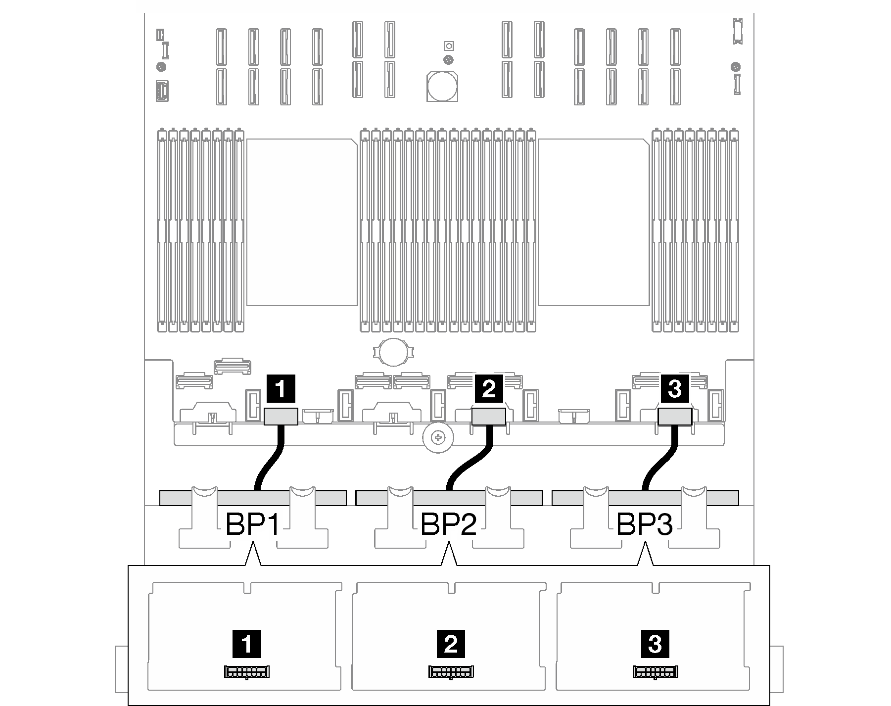
2.5-inch drive backplane cable routing (server model with four PCIe risers)
Follow the instructions in this section to learn how to do 2.5-inch drive backplane cable routing for the server model with four PCIe risers.
Before starting power cable routing for the 2.5-inch drive backplanes, remove the following components:
- Remove the fans. See Remove a fan.
- Remove the fan cage. See Remove the fan cage.
Power cable routing
Figure 1. Power cable routing for the 2.5-inch drive backplanes


| Cable | From | To |
|---|---|---|
| 1 | Backplane 1: Power connector | System board assembly: BP2 PWR connector |
| 2 | Backplane 2: Power connector | System board assembly: BP4 PWR connector |
| 3 | Backplane 3: Power connector | System board assembly: BP6 PWR connector |
Signal cable routing
Refer to the corresponding cable routing guide for related types of backplane:
Give documentation feedback