システム・ボード・アセンブリーの交換 (トレーニングを受けた技術員のみ)
システム・ボード・アセンブリーの取り外しと取り付けを行うには、このセクションの説明に従ってください。
重要
このタスクの実行は、Lenovo Service によって認定済みのトレーニングを受けた技術員が行う必要があります。適切なトレーニングおよび認定を受けずに部品の取り外しまたは取り付けを行わないでください。
注意
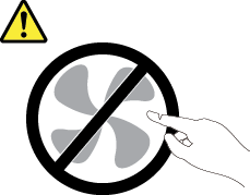
危険な稼働部品指や体の他の部分を触れないようにしてください。
注意

ヒートシンクおよびプロセッサーは、高温になる場合があります。サーバー・カバーを取り外す前に、サーバーの電源をオフにし、サーバーが冷えるまで数分間待ちます。
次の図は、ファームウェアおよび RoT セキュリティー・モジュール、システム I/O ボードとプロセッサー・ボードが搭載されたシステム・ボード・アセンブリーのレイアウトを示しています。
図 1. システム・ボード・アセンブリーのレイアウト
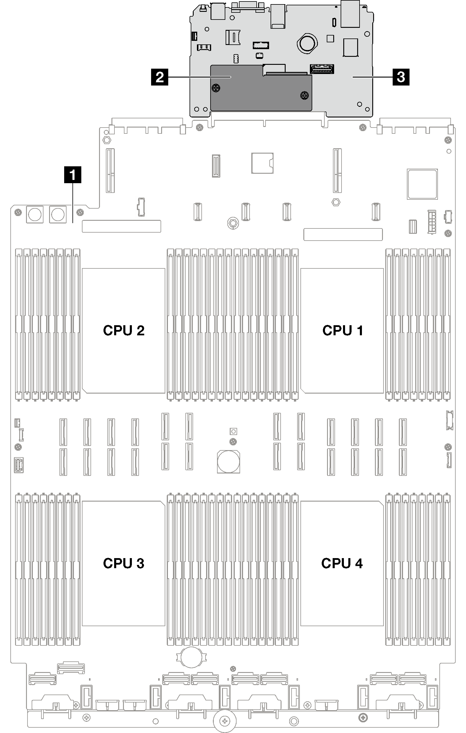
| 1 プロセッサー・ボード | 2 ファームウェアおよび RoT セキュリティー・モジュール | 3 システム I/O ボード |
フィードバックを送る