System-board-assembly switches
The following illustration indicates the location of the switches on the server.
Important
Before you change any switch settings or move any jumpers, turn off the server; then, disconnect all power cords and external cables. Review the following information:
- Any system-board-assembly switch or jumper block that is not shown in the illustrations in this document are reserved.
Note
If there is a clear protective sticker on the top of the switch blocks, you must remove and discard it to access the switches.
Figure 1. System-board-assembly switches
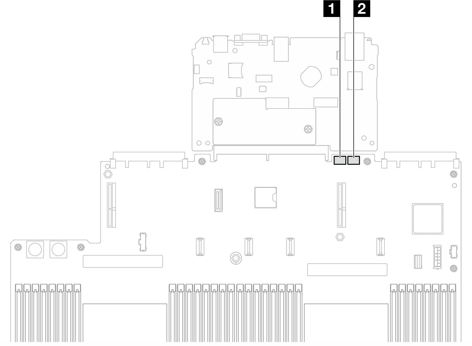
| 1 SW3 | 2 SW4 |
SW3 switch block
The following table describes the functions of the SW3 switch block on the system board assembly.
| Switch number | Default position | Description |
|---|---|---|
| 1 | Off | Reserved |
| 2 | Off | Changing this switch to the On position to resets the RTC. A momentary toggle is all that is required. To avoid excessive CMOS battery drain, do not leave this switch in the On position. |
| 3 | Off | Changing this switch to the On position overrides the power-on password. Changing the position of this switch does not affect the administrator password check if an administrator password is set. |
| 4 | Off | Changing the switch to the On position to enable ME boots to recovery. |
| 5 | Off | Reserved |
| 6 | Off | Reserved |
| 7 | Off | Reserved |
| 8 | Off | Reserved |
SW4 switch block
The following table describes the functions of the SW4 switch block on the system board assembly.
| Switch number | Default position | Description |
|---|---|---|
| 1 | Off | When the switch is in the default Off position, the server will boot by using the primary XClarity Controller firmware. Change this switch to the On position, to enable the server to boot by using a backup of the XClarity Controller firmware. |
| 2 | Off | Changing this switch to the On position to bypass the operational firmware image and performs a BMC firmware update, if the normal firmware update procedure results in an inoperative BMC. Note Use this switch only if the normal firmware update procedure fails and the operational firmware image is corrupted. Use of this switch disables normal baseboard management controller operation. |
| 3 | Off | Reserved |
| 4 | Off | Changing the switch to the On position resets the XClarity Controller. |
| 5 | Off | Reserved |
| 6 | Off | Reserved |
| 7 | Off | Reserved |
| 8 | Off | Reserved |
Give documentation feedback