System I/O board and interposer assembly connectors for cable routing
The following illustrations show the internal connectors on the System I/O board and interposer assembly that are used for internal cable routing.
Figure 1. System I/O board and interposer assembly connectors
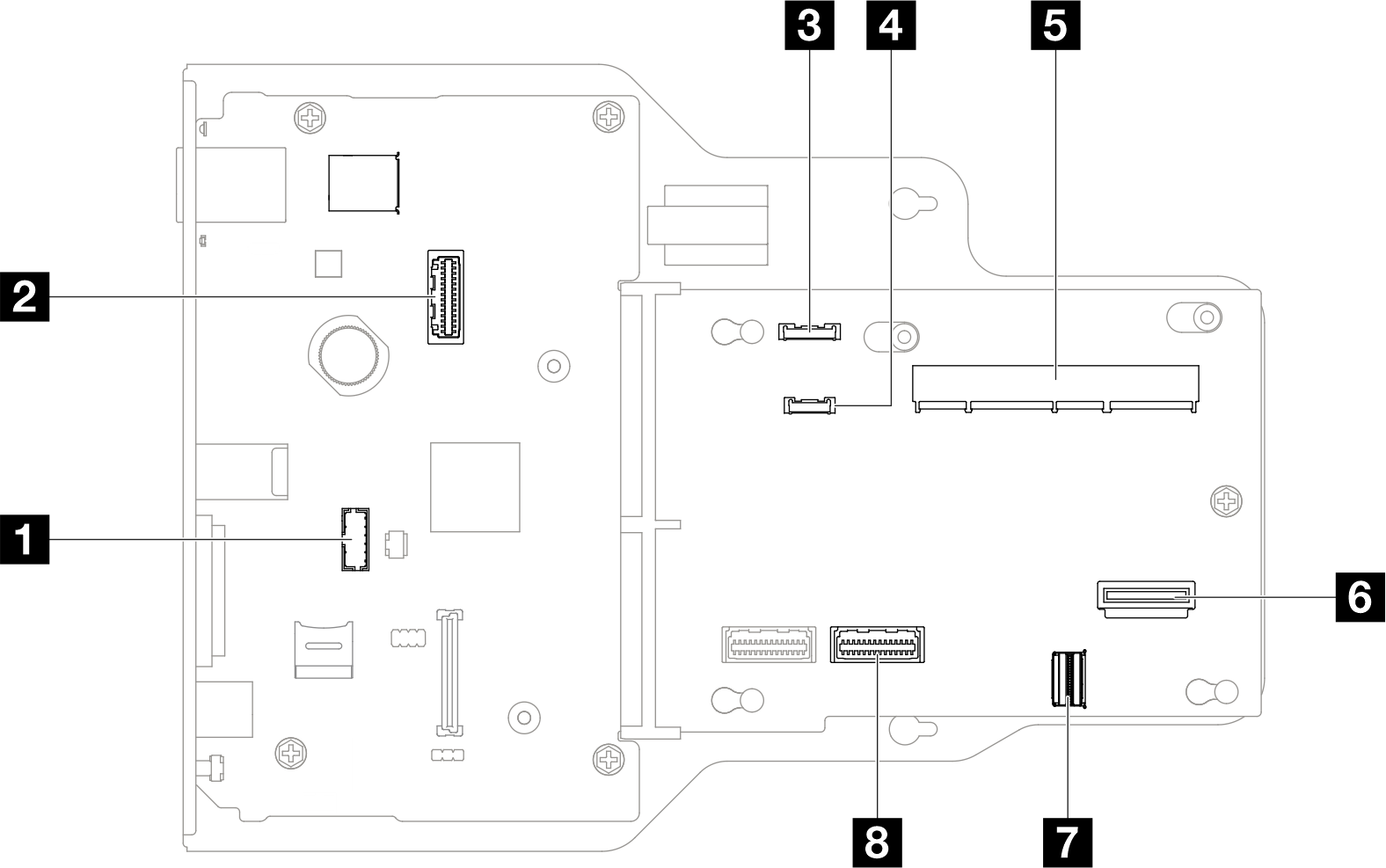
1 Serial port module connector | 5 SCM connector |
2 Second management Ethernet connector | 6 Rear OCP connector |
3 Front operator panel connector | 7 Rear Ethernet card connector |
4 External diagnostics connector | 8 PHY 2 connector |
Give documentation feedback