Light path diagnostics
Light path diagnostics is a system of LEDs on various external and internal components of the server that leads you to the failed component. When an error occurs, LEDs are lit on the front operator panel on the front of the server, then on the failed component. By viewing the LEDs in a particular order, you can often identify the source of the error.
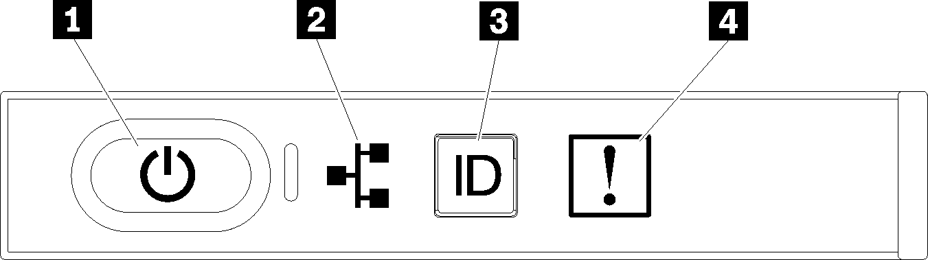
Operator panel light path LEDs
| LED | Description | Action |
|---|---|---|
| 1 Power button and power LED | Indicates power status of the server. | Not used for troubleshooting server beyond providing power status. See Front operator panel for additional information. |
| 2 Network activity LED | Indicates activity between the server and the Ethernet LAN. | Not used for troubleshooting server beyond providing network activity status. See Front operator panel for additional information. |
| 3 System ID LED (blue) | This LED is used as a presence detection LED. You can use Lenovo XClarity Controller to light this LED remotely. | Use this LED to locate the server among other servers visually. |
| 4 System-error LED (amber) | LED on: An error has occurred. |
|
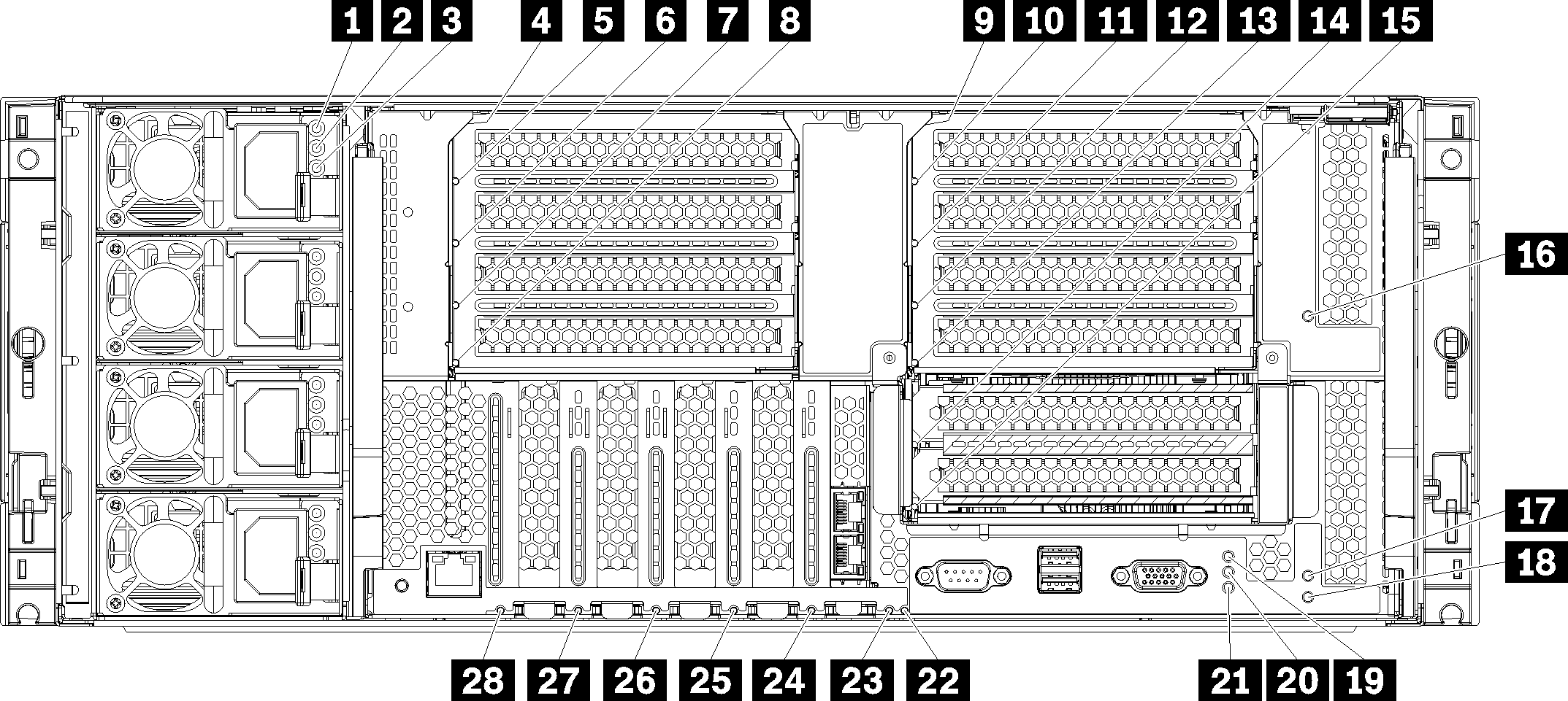
Rear light path LEDs
| LED | Description | Action |
|---|---|---|
| 1 Power supply AC power input LED (green) | Status of power supply AC power input. See Power supply LEDs for detailed descriptions of the power supply LEDs. | See Power supply LEDs for actions relating to the power supply LEDs. |
| 2 Power supply DC power output LED (green) | Status of power supply DC power output. See Power supply LEDs for detailed descriptions of the power supply LEDs. | See Power supply LEDs for actions relating to the power supply LEDs. |
| 3 Power supply fault LED (yellow) | Indicates a power supply malfunction. See Power supply LEDs for detailed descriptions of the power supply LEDs. | See Power supply LEDs for actions relating to the power supply LEDs. |
| 5, 6, 7, 8, 10, 11, 12, 13, 14, 15, 16, 17, 24, 25, 26, 27, 28 Adapter error LEDs | Indicates a malfunction for the associated adapter. |
|
| 4, 9, 18 Riser error LEDs | Indicates a malfunction for the associated riser or an adapter installed in the riser. |
|
| 19 Power LED (green) | Indicates the power state of the server. | Not used for troubleshooting server beyond providing power status. See power supply LEDs (1, 2, and 3) for additional information. |
| 20 System ID LED (blue) | This LED is used as a presence detection LED. You can use Lenovo XClarity Controller to light this LED remotely. | Use this LED to locate the server among other servers visually. |
| 21 System-error LED (amber) | Indicates an error has occurred. |
|
| 22 3v fault (system battery) LED | Indicates a malfunction or low voltage for the 3V system battery (CR2032) in the I/O tray. |
|
| 23 I/O-board fault LED | Indicates a malfunction for the I/O board or an adapter installed in the I/O board. |
|