System-board LEDs
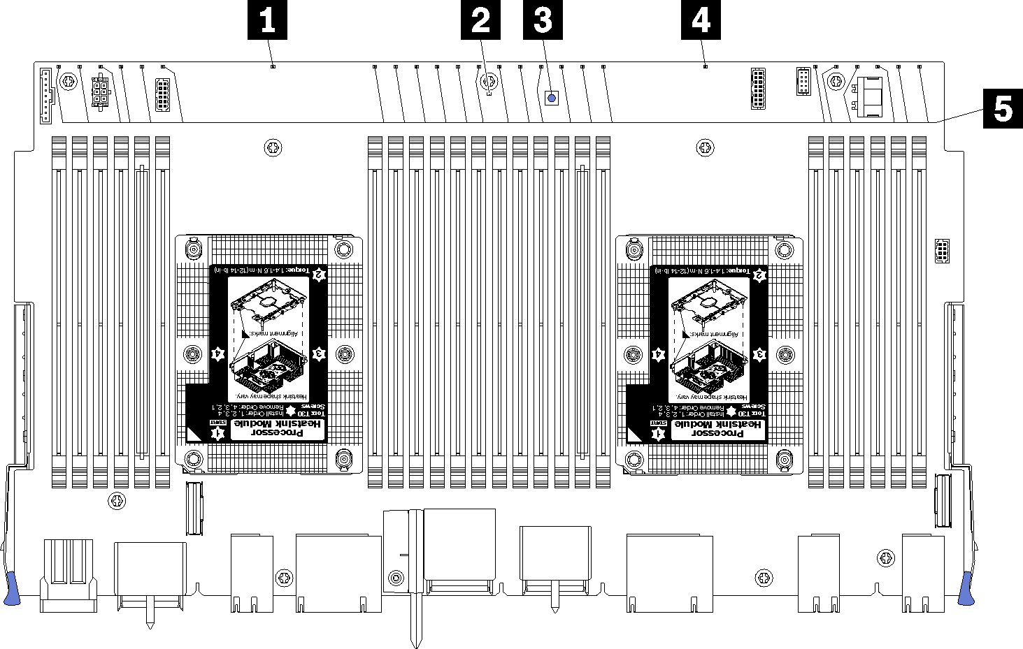
The following illustration shows the location of light path diagnostic LEDs and light path diagnostic switch on the system board. These LEDs can often identify the source of an error.
Press the light path diagnostic switch 3 to turn on the system board LEDs for a limited amount of time when the system board is removed from the chassis.
Figure 1. System-board light path LEDs


| LED | Description | Action |
|---|---|---|
| 1 Processor 2 error LED | LED on: An error has occurred with processor 2. | |
| 2 System board error LED | LED on: An error has occurred on the system board. | Complete the following steps:
|
| 3 Light path diagnostic switch | Press the light path diagnostic switch to turn on the system board LEDs. | |
| 4 Processor 1 error LED | LED on: An error has occurred with processor 1. | |
| 5 Memory module 1 through 24 error LEDs | LED on: An error has occurred with the designated memory module. | See Memory problems |
Give documentation feedback