Install the heat sink and the fan module
Follow instructions in this section to install the heat sink and the fan module. This procedure must be executed by a trained technician.
About this task
To avoid potential danger, read and follow the following safety statements.
- S002
 CAUTIONThe power-control button on the device and the power switch on the power supply do not turn off the electrical current supplied to the device. The device also might have more than one power cord. To remove all electrical current from the device, ensure that all power cords are disconnected from the power source.
 - S009
 CAUTIONTo avoid personal injury, disconnect the fan cables before removing the fan from the device.
 - S014
 CAUTIONHazardous voltage, current, and energy levels might be present. Only a qualified service technician is authorized to remove the covers where the label is attached.
 - S017CAUTIONHazardous moving fan blades nearby. Keep fingers and other body parts away.
- S033
 CAUTION
Hazardous energy present. Voltages with hazardous energy might cause heating when shorted with metal, which might result in spattered metal, burns, or both.
Attention
Read the Installation guidelines to ensure that you work safely.
Touch the static-protective package that contains the component to any unpainted metal surface on the server; then, remove it from the package and place it on a static-protective surface.
Procedure
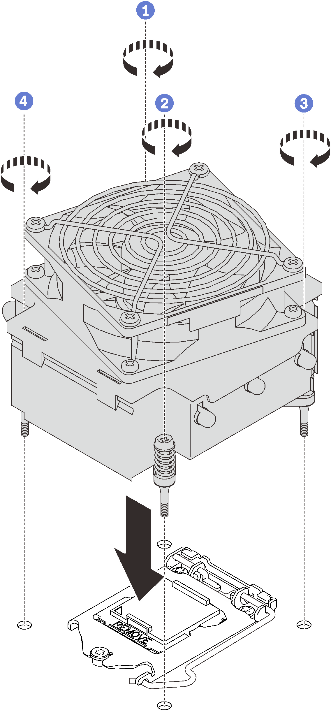
- Install the heat sink and fan module.Figure 1. Installing the heat sink and the fan module
 &
&  Tighten screw 1 and 2: First, partially tighten screw 1; then, fully tighten screw 2. Finally, fully tighten screw 1.
 &
&  Tighten screw 3 and 4: First, partially tighten screw 3; then, fully tighten screw 4. Finally, fully tighten screw 3.
After this task is completed
Complete the parts replacement. See Complete the parts replacement.
Demo video
Give documentation feedback