System-board components
The illustration in this section shows the component locations on the system board.
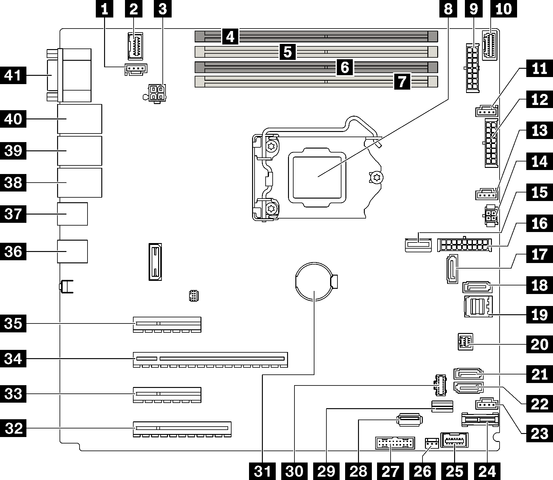
Figure 1. System board components
| Callout | Callout | ||
|---|---|---|---|
| 1 | Rear fan connector | 22 | SATA 4 |
| 2 | Front VGA connector | 23 | Fan 4 connector for front fan |
| 3 | Processor power connector | 24 | TPM/TCM connector |
| 4 | DIMM Slot 1 | 25 | Front panel connector |
| 5 | DIMM Slot 2 | 26 | Intrusion switch connector |
| 6 | DIMM Slot 3 | 27 | Front USB connector |
| 7 | DIMM Slot 4 | 28 | Internal USB 3.2 Gen 1 connector |
| 8 | Processor socket | 29 | M.2 signal connector |
| 9 | Backplane 1 power connector | 30 | M.2 power connector |
| 10 | Power distribution board side band connector | 31 | CMOS battery |
| 11 | Fan 1 connector for front fan | 32 | PCIe Slot 4 |
| 12 | Backplane 2 power connector | 33 | PCIe Slot 3 |
| 13 | Fan 2 connector for processor | 34 | PCIe Slot 2 |
| 14 | Optical/tape drive power connector | 35 | PCIe Slot 1 |
| 15 | System power connector | 36 | Two USB 3.2 Gen 2 connectors |
| 16 | MCIO x4 connector for NVMe | 37 | Two USB 3.2 Gen 2 connectors |
| 17 | SATA 6 | 38 | Ethernet connector 2 |
| 18 | SATA 7 | 39 | Ethernet connector 1 (shared with XCC network port) |
| 19 | SATA 0 to 3 | 40 | Lenovo XClarity Controller(XCC) management port |
| 20 | SGPIO1 connector | 41 | VGA and serial port connector |
| 21 | SATA 5 | ||
Give documentation feedback