System-board jumpers and buttons
The illustration in this section shows the location of the jumpers and buttons on the server.
Note
If there is a clear protective sticker on the top of the switch blocks, you must remove and discard it to access the switches.
Figure 1. System-board jumpers and buttons
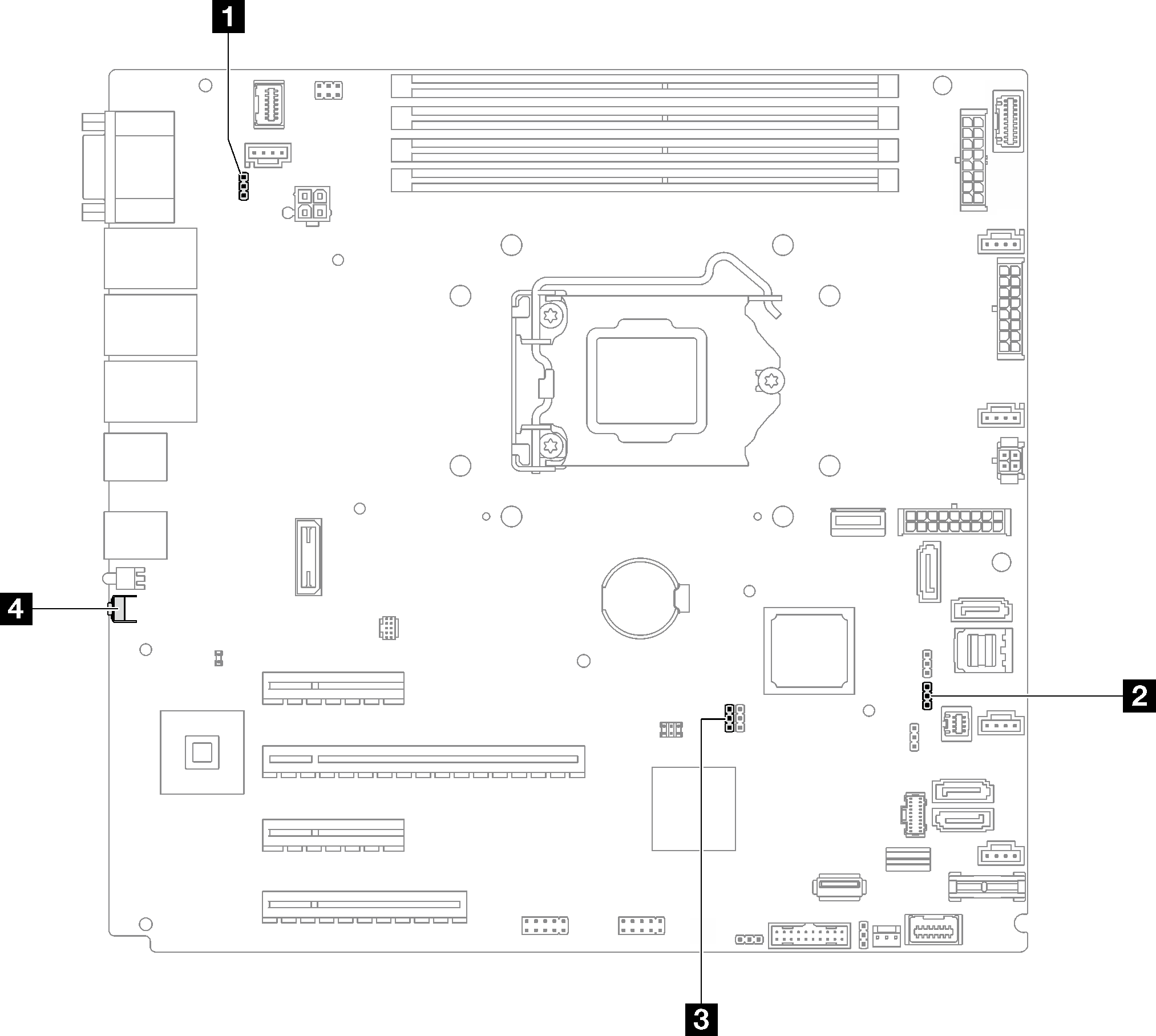
The following table describes the jumpers and buttons on the system board.
| Jumper and button name | Jumper setting / Button function |
|---|---|
| 1 Power permission override jumper |
|
| 2 Force Lenovo XClarity Controller update jumper |
|
| 3 Clear CMOS jumper |
|
| 4 Force NMI button | This button is on the rear of the server. Press this button to force a nonmaskable interrupt to the processor. You might have to use a pen or the end of a straightened paper clip to press the button. You can also use it to force a blue-screen memory dump (use this button only when you are directed to do so by Lenovo Support). |
Important
- Before you change any switch settings or move any jumpers, turn off the server; then, disconnect all power cords and external cables. Review the information in Safety Information page, Installation guidelines, Handling static-sensitive devices, and Power off the server.
- Any system-board switch or jumper block that is not shown in the illustrations in this document are reserved.
Give documentation feedback