Front view
The front view of the server varies by model.
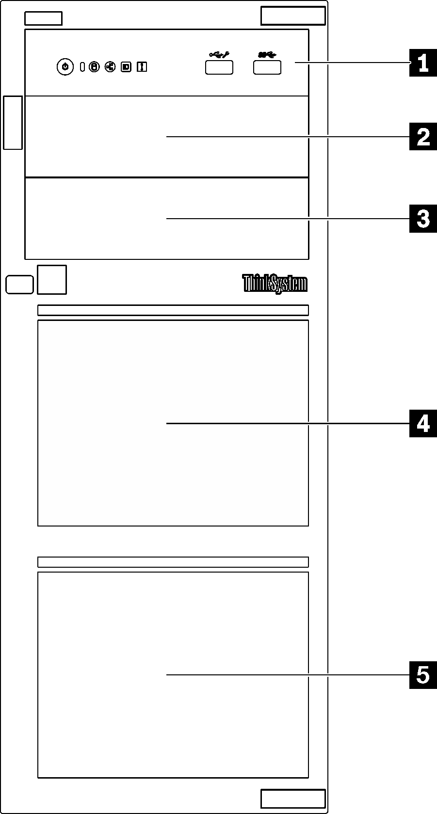
The following illustration shows the server components that may appear on the front of this server model.
Figure 1. Front view of the server components
| Item | Description |
|---|---|
| 1 Front panel | See Front panel |
| 2 Optical-drive bay 2 | The optical drive bay 2 supports an optical drive. |
| 3 Optical-drive bay 1 | The optical drive bay 1 supports an optical drive or a tape drive (RDX or LTO). |
| 4 5 Storage drive bays | The number of available drive bays varies by model. See Drive configurations for the complete configuration table. The vacant drive bays must be installed with drive fillers. |
Drive configurations
| Item |
|
|
|
|
|
| 2 | N/A | Optical-drive bay 2: Optical drive | Optical-drive bay 2: Optical drive | Optical-drive bay 2: Optical drive | Optical-drive bay 2: Optical drive |
| 3 | N/A | Optical-drive bay 1: Optical/tape drive | Optical-drive bay 1: Optical/tape drive | Optical-drive bay 1: Optical/tape drive | Optical-drive bay 1: Optical/tape drive |
| 4 | Three SATA drives (Bay 4, 5, 6) and one SATA/NVMe drive (Bay 7) | Two SATA drives (Bay 4, 5) | Four SAS/SATA drives (Bay 4 to 7) | Eight SAS/SATA drives (Bay 8 to 15) | Eight SAS/SATA drives (Bay 4 to 11) |
| 5 | Four SATA drives (Bay 0 to 3) | Four SATA drives (Bay 0 to 3) | Four SAS/SATA drives (Bay 0 to 3) | Eight SAS/SATA drives (Bay 0 to 7) | Four SAS/SATA drives (Bay 0 to 3) |
Give documentation feedback