Remove the heat sink and fan module (trained technician only)
Follow instructions in this section to remove the heat sink and fan module. The procedure must be executed by a trained technician.
About this task
S002
CAUTION
The power-control button on the device and the power switch on the power supply do not turn off the electrical current supplied to the device. The device also might have more than one power cord. To remove all electrical current from the device, ensure that all power cords are disconnected from the power source.
Attention
- Read Installation Guidelines and Safety inspection checklist to ensure that you work safely.
- Power off the server and peripheral devices and disconnect the power cords and all external cables. See Power off the server.
- If the server is in a rack, remove it from the rack. See Remove the server from rack.
- Remove any locking device that secures the server, such as a Kensington lock or a padlock.
- Place the server on its side with the cover up.
Procedure
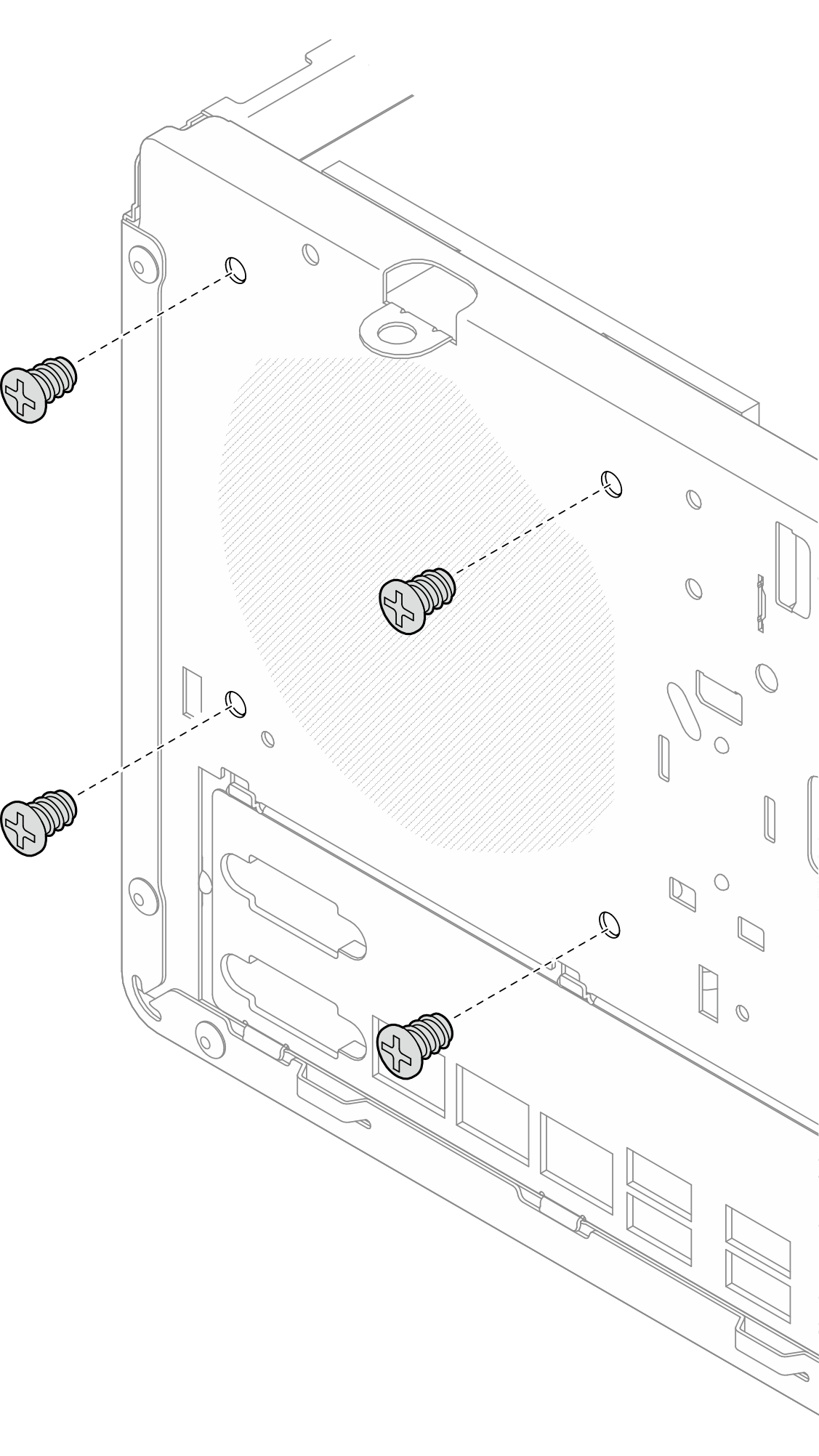
- If the server is installed with processor with 95W TDP, the heat sink fan is installed on the rear side of the chassis. Remove the four securing screws from outside of the chassis.Figure 1. Removing the four screws securing the heat sink fan to the chassis
- Remove the heat sink and fan module.
 &
&  Loosen screw 1 and 2: First, partially loosen screw 1; then, fully loosen screw 2. Finally, fully loosen screw 1.
 &
&  Loosen screw 3 and 4: First, partially loosen screw 3; then, fully loosen screw 4. Finally, fully loosen screw 3.
 Lift evenly and remove the heat sink and fan module from the server.
NoteGently remove the four screws to avoid any possible damage to the system board.
Always keep the four screws attached to the heat sink and fan module.
Do not touch the thermal grease while handling the heat sink and fan module.
Figure 2. Loosening the screws on the heat sink and fan module for processor with TDP lower than 95W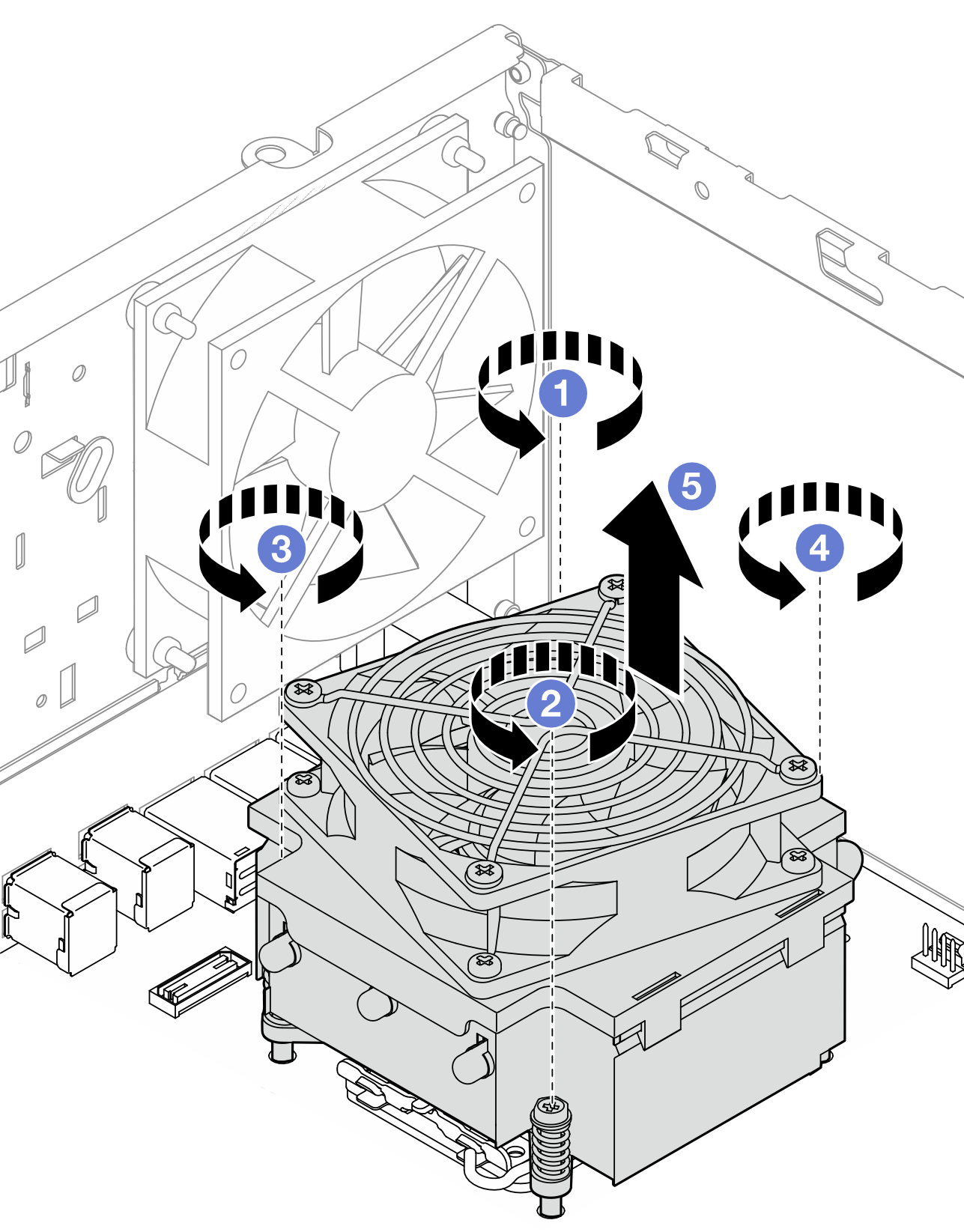 Figure 3. Loosening the screws on the heat sink and fan module for processor with 95W TDP
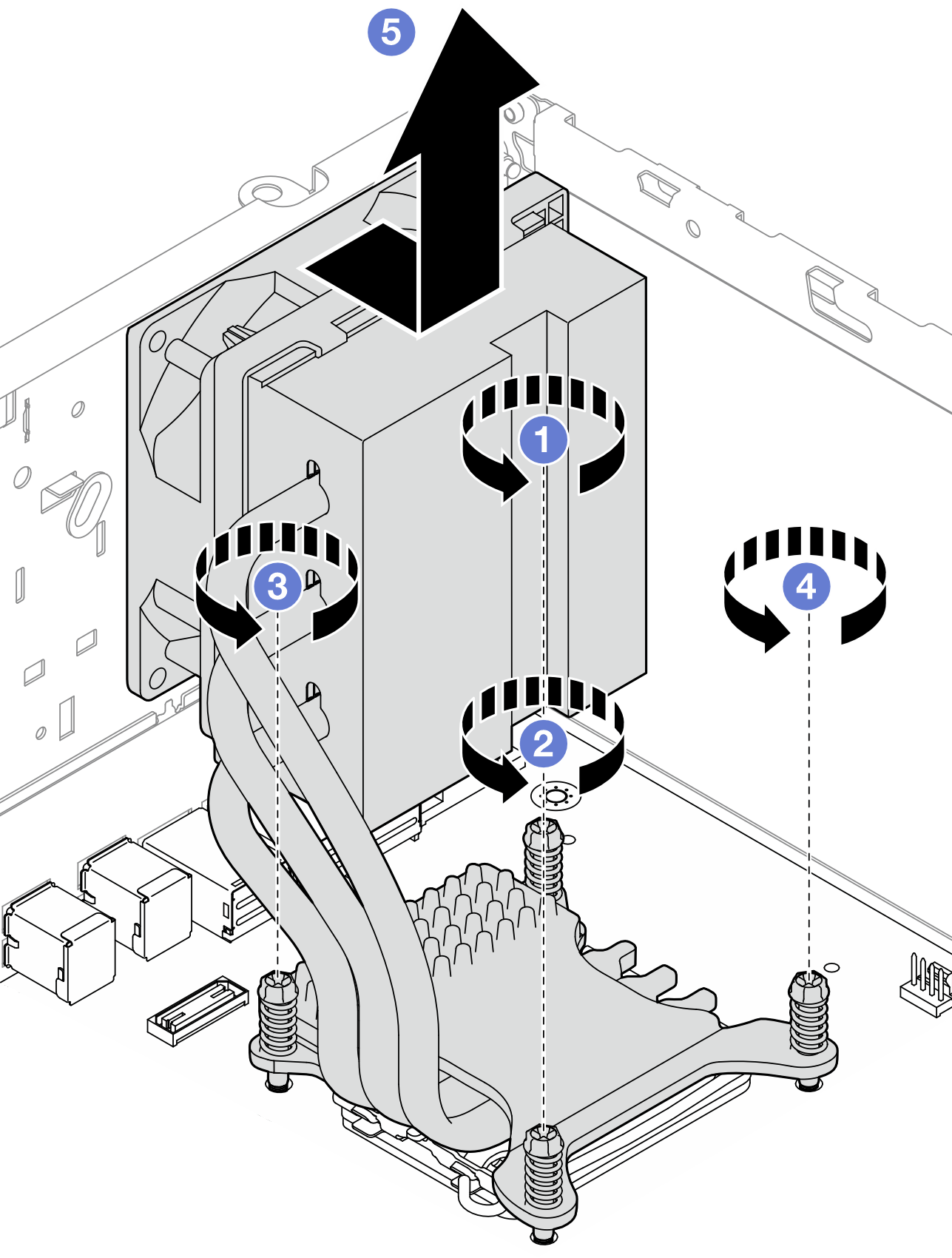
After you finish
Install a replacement unit. See Install the heat sink and fan module (trained technician only).
If you are instructed to return the component or optional device, follow all packaging instructions, and use any packaging materials for shipping that are supplied to you.
Demo video
Give documentation feedback