Firmware and RoT security module LEDs
The following illustration shows the light-emitting diodes (LEDs) on the ThinkSystem V3 Firmware and Root of Trust Security Module (Firmware and RoT security module).
Figure 1. LEDs on the firmware and RoT security module
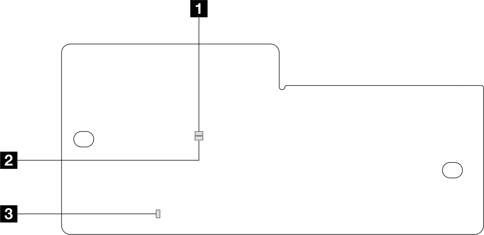
| 1 AP0 LED (Green) | 2 AP1 LED (Green) | 3 Fatal Error LED (Amber) |
| Scenario | AP0 LED | AP1 LED | Fatal Error LED | FPGA heartbeat LED | XCC heartbeat LED | Actions |
|---|---|---|---|---|---|---|
| RoT security module fatal firmware failure | Off | Off | On | N/A | N/A | Replace the firmware and RoT security module. |
| Blink | N/A | On | N/A | N/A | Replace the firmware and RoT security module. | |
| No system power (FPGA heartbeat LED off) | Off | Off | Off | Off | Off | If the AC power is on, but the system board assembly does not have power, then:
|
| XCC firmware recoverable error | Blink | N/A | Off | N/A | N/A | Information only. No action is required. |
| XCC firmware is recovered from error | Blink | N/A | Off | N/A | N/A | Information only. No action is required. |
| UEFI firmware authentication failure | N/A | Blink | Off | N/A | N/A | Information only. No action is required. |
| UEFI firmware is recovered from authentication failure | N/A | On | Off | N/A | N/A | Information only. No action is required. |
| System is OK (FPGA heartbeat LED is On) | On | On | Off | On | Blink (1 Hz) | Information only. No action is required. |
Note
For locations of the FPGA LED and XCC heartbeat LED, see System board LEDs.
Give documentation feedback