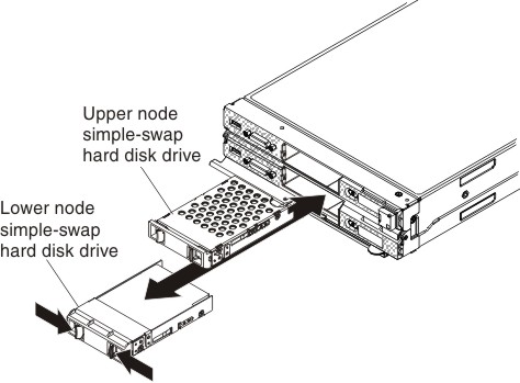
Installing a simple-swap hard disk drive
Use this information to install a simple-swap hard disk drive. The Flex System x222 Compute Node can use 2.5-inch simple-swap hard disk drives of either the standard or solid-state drive (SSD) design. Simple-swap hard disk drives can be installed in both the upper and lower compute nodes.
Important
Simple-swap hard disk drives are not hot-swap devices and must be removed or installed with the compute node turned off. For information about installing optional 1.8-inch hot-swap solid-state drives, see Installing a solid state drive.
Before you remove a simple-swap hard disk drive, complete the following steps.
- Read Safety and Installation guidelines.
- If the compute node where you are installing the simple-swap hard disk drive is operating, shut down its operating system.
- Press the power button to turn off the compute node where you are installing the simple-swap hard disk drive (see Turning off a compute node for more information).
The upper and lower compute nodes each have one SATA hard disk drive bay for installing a simple-swap hard disk drive.
Note
- You can install multiple solid state drives (SSDs) in an upper or lower compute node if an optional solid state drive mounting sleeve is installed in the upper or lower compute node.
- Each compute node can support RAID level-0 (striping), when a single hard disk drive is installed in an upper or lower compute node, or RAID level-1 (mirroring), when two 1.8-inch solid-state drives are installed in an upper or lower compute node. See Configuring a RAID array for information about RAID configuration.
To install a simple-swap hard disk drive or hard disk drive bay filler, complete the following steps.

Give documentation feedback