Installing a DVD drive
Use this information to install a DVD drive.
If you are replacing a drive, make sure that:
- You have all the cables and other equipment that are specified in the documentation that comes with the new drive.
- You have checked the instructions that come with the new drive to determine whether you must set any switches or jumpers in the drive.
- You have removed the optical drive rail from the side of the old drive and have them available for installation on the new drive.
Note
- If you are installing a new DVD drive on the optical drive bay 2, an EMC shield should be removed firstly to continue the installation.
- If you are installing a drive that contains a laser, observe the following safety precautions.
Statement 3

CAUTION
When laser products (such as CD-ROMs, DVD drives, fiber optic devices, or transmitters) are installed, note the following:
- Do not remove the covers. Removing the covers of the laser product could result in exposure to hazardous laser radiation. There are no serviceable parts inside the device.
- Use of controls or adjustments or performance of procedures other than those specified herein might result in hazardous radiation exposure.
DANGER
danger
Some laser products contain an embedded Class 3A or Class 3B laser diode.
Note the following. Laser radiation when open. Do not stare into the beam, do not view directly with optical instruments, and avoid direct exposure to the beam.
Read the safety information in Safety and Installation guidelines.
If you are replacing a server component in the server, you need to turn off the server and peripheral devices, and disconnect the power cords and all external cables.
To install the DVD drive, complete the following steps.
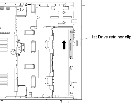
- Slide out the 1st ODD/DVD drive and tape drive retainer clip (hereafter called drive retainer clip) from the chassis for use. Figure 1. Slide out the 1st drive retainer clip
 NoteIf the 1st drive retainer clip has been used, slide out the 2nd drive retainer clip for use. If you need an additional drive retainer clip, you can purchase it from Lenovo. For the part number of the drive retainer clip, see
Structural parts. Figure 2. Slide out the 2nd drive retainer clip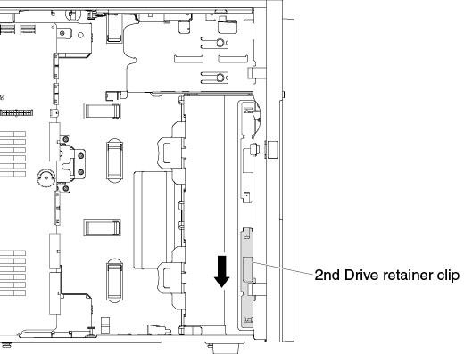
- Install one drive retainer clip only to the left side of DVD drive, using the holes nearest the center of the drive. For the part number of the drive retainer clip, see Structural parts.Figure 3. Install the drive retainer clip
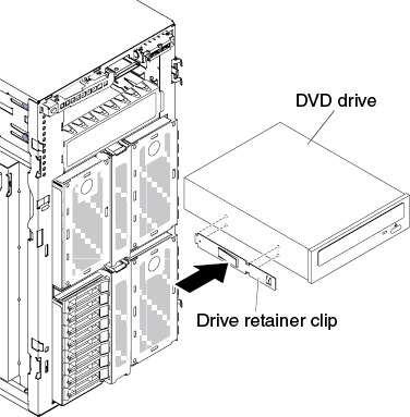
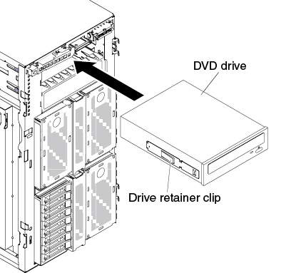
- Align the rail on the DVD drive with the guides in the drive bay; then, slide the DVD drive into the drive bay until it clicks into place.Figure 4. Slide the DVD drive into the drive bay
Note
In order to ensure that the ODD/DVD drive can eject smoothly and avoid damage, remove the bezel filler. See Figure 3.
If you have other devices to install or remove, do so now. Otherwise, go to Completing the installation.
Give documentation feedback