Removing a microprocessor and heat sink

Use this information to remove a microprocessor and heat sink from the blade server. For related information for the DataPower Integration Blade XI50B blade appliance, see the IBM WebSphere DataPower Integration Blade XI50B Type 4195 Installation and User's Guide.

Read the following important guidelines before you remove a microprocessor that is not faulty (for example, when you are replacing the system-board assembly).

If you are not replacing a defective heat sink or microprocessor, the thermal material on the heat sink and microprocessor will remain effective if you carefully handle the heat sink and microprocessor when you remove or install these components. Do not touch the thermal material or otherwise allow it to become contaminated.

Note
  1. The microprocessor and heat sink assembly are both field-replaceable units (FRUs) and must be replaced by a trained service technician. To contact an IBM service representative, see Hardware service and support.
  2. The heat-sink FRU is packaged with the thermal material applied to the underside. This thermal material is not available as a separate FRU. You must replace the heat sink when new thermal material is required, such as when a defective microprocessor is replaced or if the thermal material is contaminated or has come in contact with another object other than its paired microprocessor.
  3. A heat-sink FRU can be ordered separately if the thermal material becomes contaminated.

To remove a microprocessor, complete the following steps.
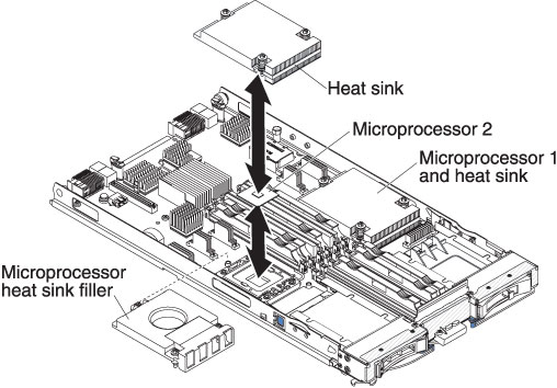

Graphic illustrating the removal of a microprocessor and heat sink
  1. Before you begin, read Safety and Installation guidelines.
  2. If the blade server is installed in a BladeCenter unit, remove it (see Removing the blade server from the BladeCenter unit for instructions).
  3. Remove the blade server cover (see Removing the blade server cover for instructions).
  4. If an optional expansion unit is installed, remove the expansion unit (see Removing an optional expansion unit).
  5. Locate the microprocessor that will be removed (see Blade server connectors).
  6. Before removing the microprocessor, you must remove the memory module closest to the microprocessor.
    1. If you are removing microprocessor 1, remove the memory module or DIMM filler from DIMM connector 1 (see Removing a memory module).
    2. If you are removing microprocessor 2, remove the memory module or DIMM filler from DIMM connector 6 (see Removing a memory module).
  7. Remove the heat sink.
    Attention
    Do not touch the thermal material on the bottom of the heat sink. Touching the thermal material will contaminate it. If the thermal material on the microprocessor or heat sink becomes contaminated, you must replace the heat sink.
    1. Loosen the screw on one side of the heat sink to break the seal with the microprocessor.
    2. Use a screwdriver to loosen the screws on the heat sink, rotating each screw two full turns until each screw is loose.
    3. Use your fingers to gently pull the heat sink from the microprocessor.
    Attention
    Do not use any tools or sharp objects to lift the release lever on the microprocessor socket. Doing so might result in permanent damage to the system board.

    Graphic illustrating the microprocessor and heat sink
  8. Rotate the locking lever on the microprocessor socket from its closed and locked position until it stops in the fully open position (approximately a 135° angle). Lift the microprocessor retainer cover upward.
    Attention
    Do not touch the microprocessor contacts; handle the microprocessor by the edges only. Contaminants on the microprocessor contacts, such as oil from your skin, can cause connection failures between the contacts and the socket.
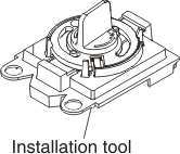
  9. Find the microprocessor installation tool that came with the new microprocessor.

    Graphic illustrating the microprocessor tool.
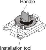
  10. Twist the handle on the microprocessor tool counterclockwise so that it is in the open position.

    Graphic illustrating the microprocessor tool being used to attach to the microprocessor.
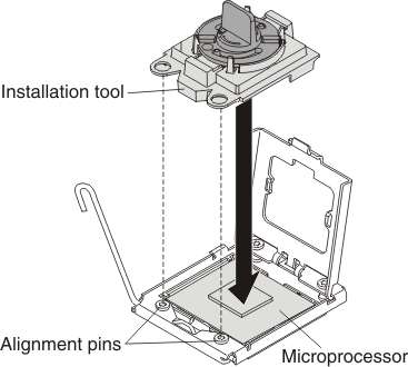
  11. Place the microprocessor installation tool down over the microprocessor, aligning the holes on the tool with the screws on the microprocessor bracket.
    Note
    The alignment holes on the tool will not sit flush on the microprocessor bracket screws. However, the holes can be used as a guide to ensure the proper alignment between the microprocessor installation tool and the microprocessor bracket.

    Graphic illustrating the microprocessor tool being used to attach to the microprocessor.
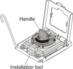
  12. Twist the handle clockwise to attach the tool to the microprocessor.
    Note
    You can pick up or release the microprocessor by twisting the microprocessor installation tool handle.

    Graphic illustrating the microprocessor tool being used to attach to the microprocessor.
  13. Carefully lift the microprocessor straight up and out of the socket, and place it on a static-protective surface.
  14. If you are instructed to return the microprocessor and heat sink, follow all packaging instructions, and use any packaging materials for shipping that are supplied to you.