Installing a DIMM - IBM MAX5
The expansion blade has a total of 24 dual inline memory module (DIMM) connectors. The expansion blade supports 2 GB (Type 7873 models), 4 GB, 8 GB, 16 GB (Type 7873 models), and 32 GB (Type 7873 models) memory DIMMs. Typically, you will install all memory supported by the BladeCenter HX5 blade server before installing memory in the IBM MAX5 expansion blade.
There are two versions of the IBM MAX5 expansion blade, referred to as the IBM MAX5 version 1 and IBM MAX5 version 2 in this document. IBM MAX5 version 2 has a "MAX5" identifying label on the bottom of the front bezel. The functionality of the two IBM MAX5 expansion blades are equivalent except the type of DIMMs supported. The type of DIMMs supported will differ, depending on the version of IBM MAX5 expansion blade installed.
| Description | CRU part number |
|---|---|
| Intel Xeon E7-2830 Processor, 2.13GHz/24M/6.4GT/s, 8C, 105W | 69Y3075 |
| Intel Xeon E7-2850 Processor, 2.00GHz/24M/6.4GT/s, 10C, 130W | 69Y3085 |
| Intel Xeon E7-2860 Processor, 2.26GHz/24M/6.4GT/s, 10C, 130W | 69Y3095 |
| Intel Xeon E7-4830 Processor, 2.13GHz/24M/6.4GT/s, 8C, 105W | 88Y6083 |
| Intel Xeon E7-4850 Processor, 2.00GHz/24M/6.4GT/s, 10C, 130W | 88Y6093 |
| Intel Xeon E7-4860 Processor, 2.26GHz/24M/6.4GT/s, 10C, 130W | 88Y6103 |
| Intel Xeon E7-8837 Processor, 2.67GHz/24M/6.4GT/s, 8C, 130W | 88Y6113 |
| Intel Xeon E7-8867L Processor, 2.13GHz/30M/6.4GT/s, 10C, 105W | 88Y6125 |
| Intel Xeon E7-2870 Processor, 2.40GHz/30M/6.4GT/s, 10C, 130W | 88Y6151 |
| Intel Xeon E7-4870 Processor, 2.40GHz/30M/6.4GT/s, 10C, 130W | 88Y6161 |
Depending on the memory mode that is set in the Setup utility, the expansion blade can support a minimum of 4 GB and a maximum of 768 GB of system memory. For a current list of supported DIMMs for the expansion blade, see thehttp://www.ibm.com/ servers/eserver/serverproven/compat/us/.
| DIMM Grouping A All DIMMs in this group must be the same technology (DRAM size, such as 2 Gbit) | ||
| DIMM 1, DIMM 8 | DIMM 2, DIMM 7 | All DIMMs must be the same DRAM width (such as 4R x 8) |
| DIMM 3, DIMM 6 | DIMM 4, DIMM 5 | All DIMMs must be the same DRAM width (such as 4R x 8) |
| DIMM Grouping B All DIMMs in this group must be the same technology (DRAM size, such as 2 Gbit) | ||
| DIMM 13, DIMM 17 | DIMM 14, DIMM18 | All DIMMs must be the same DRAM width (such as 4R x 8) |
| DIMM 15, DIMM 19 | DIMM 16, DIMM 20 | All DIMMs must be the same DRAM width (such as 4R x 8) |
| DIMM Grouping C All DIMMs in this group must be the same technology (DRAM size, such as 2 Gbit) | ||
| DIMM 9, DIMM 21 | DIMM 10, DIMM 22 | All DIMMs must be the same DRAM width (such as 4R x 8) |
| DIMM 11, DIMM 23 | DIMM 12, DIMM 24 | All DIMMs must be the same DRAM width (such as 4R x 8) |
- Each DIMM pair must be the exact same size and speed. For example, DIMM 1 and DIMM 8 must be the same size and speed. DIMM 2 and DIMM 7 must be the same size and speed. However, DIMM 1 and DIMM 2 have to be the same technology, but they do not need to be the same size and speed.
- When populating the IBM MAX5, use the DIMMs with the greatest size first. For example, install all 8 GB DIMMs before you install 4 GB DIMMs. Populate the DIMMs according to the DIMM population table for your environment. See Table 3 through Table 5 for the DIMM population order.
The installation order for DIMMs depends on whether you intend to optimize the DIMM installation for performance or for power saving.
The following table lists the memory configurations and installation order to optimize the IBM MAX5 for performance.
| Installed memory | DIMM connector | |||||||||||||||||||||||
|---|---|---|---|---|---|---|---|---|---|---|---|---|---|---|---|---|---|---|---|---|---|---|---|---|
| 1 | 2 | 3 | 4 | 5 | 6 | 7 | 8 | 9 | 10 | 11 | 12 | 13 | 14 | 15 | 16 | 17 | 18 | 19 | 20 | 21 | 22 | 23 | 24 | |
| 2 DIMMs | X | X | ||||||||||||||||||||||
| 4 DIMMs | X | X | X | X | ||||||||||||||||||||
| 6 DIMMs | X | X | X | X | X | X | ||||||||||||||||||
| 8 DIMMs | X | X | X | X | X | X | X | X | ||||||||||||||||
| 10 DIMMs | X | X | X | X | X | X | X | X | X | X | ||||||||||||||
| 12 DIMMs | X | X | X | X | X | X | X | X | X | X | X | X | ||||||||||||
| 14 DIMMs | X | X | X | X | X | X | X | X | X | X | X | X | X | X | ||||||||||
| 16 DIMMs | X | X | X | X | X | X | X | X | X | X | X | X | X | X | X | X | ||||||||
| 18 DIMMs | X | X | X | X | X | X | X | X | X | X | X | X | X | X | X | X | X | X | ||||||
| 20 DIMMs | X | X | X | X | X | X | X | X | X | X | X | X | X | X | X | X | X | X | X | X | ||||
| 22 DIMMs | X | X | X | X | X | X | X | X | X | X | X | X | X | X | X | X | X | X | X | X | X | X | ||
| 24 DIMMs | X | X | X | X | X | X | X | X | X | X | X | X | X | X | X | X | X | X | X | X | X | X | X | X |
The following table lists the memory configurations and installation order to optimize the IBM MAX5 for power saving.
| Installed memory | DIMM connector | |||||||||||||||||||||||
|---|---|---|---|---|---|---|---|---|---|---|---|---|---|---|---|---|---|---|---|---|---|---|---|---|
| 1 | 2 | 3 | 4 | 5 | 6 | 7 | 8 | 9 | 10 | 11 | 12 | 13 | 14 | 15 | 16 | 17 | 18 | 19 | 20 | 21 | 22 | 23 | 24 | |
| 2 DIMMs | X | X | ||||||||||||||||||||||
| 4 DIMMs | X | X | X | X | ||||||||||||||||||||
| 6 DIMMs | X | X | X | X | X | X | ||||||||||||||||||
| 8 DIMMs | X | X | X | X | X | X | X | X | ||||||||||||||||
| Installed memory | DIMM connector | |||||||||||||||||||||||
|---|---|---|---|---|---|---|---|---|---|---|---|---|---|---|---|---|---|---|---|---|---|---|---|---|
| 1 | 2 | 3 | 4 | 5 | 6 | 7 | 8 | 9 | 10 | 11 | 12 | 13 | 14 | 15 | 16 | 17 | 18 | 19 | 20 | 21 | 22 | 23 | 24 | |
| 4 DIMMs | X | X | X | X | ||||||||||||||||||||
| 8 DIMMs | X | X | X | X | X | X | X | X | ||||||||||||||||
| 12 DIMMs | X | X | X | X | X | X | X | X | X | X | X | X | ||||||||||||
| 16 DIMMs | X | X | X | X | X | X | X | X | X | X | X | X | X | X | X | X | ||||||||
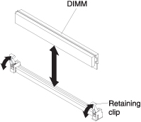
DIMM installation procedure
To install a DIMM, complete the following steps:
- To install the DIMMs, repeat the following steps for each DIMM that you install.