Installing an I/O module
You can install up to four I/O modules into the Flex System Carrier-Grade chassis. An Ethernet switch or a pass-thru module must be installed in I/O bay 1 and/or bay 2 whenever one or more compute nodes on-board Ethernet interface is active or there is an Ethernet I/O expansion card interfacing with I/O bay 1 and 2.
- Verify that the I/O module is compatible with the chassis. See the Lenovo ServerProven website.
- Read the installation instructions that come with the I/O module.
To install an I/O module, complete the following steps.
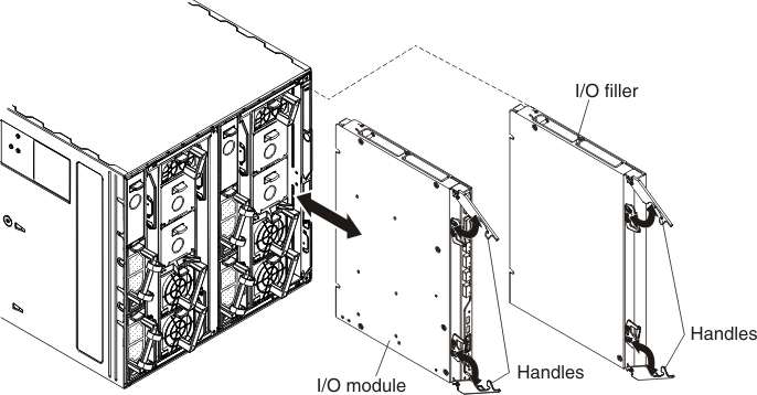
- Remove the I/O filler, if necessary. Open the release handles (rotate the top handle up and the bottom handle down).
- Slide the filler out of the bay.
- Open the release handles on the I/O module (rotate the top handle up and the bottom handle down).
- Align the I/O module with the bay on the chassis and slide the module into the module bay until it is seated.
- Close the release handles (rotate the top handle down and bottom handle up).
Warning: The intra-building port(s) (EN2092 I/O module Ethernet ports) of the equipment or subassembly are suitable for connection to intra-building or unexposed wiring or cabling only. The intra-building port(s) of the equipment or subassembly MUST NOT be metallically connected to interfaces that connect to the OSP or its wiring. These interfaces are designed for use as intra-building interfaces only (Type 2 or Type 4 ports as described in GR-1089) and require isolation from the exposed OSP cabling. The addition of Primary Protectors is not sufficient protection in order to connect these interfaces metallically to OSP wiring.