Remove bottom cable management arm (CMA)
Use this information to remove the bottom cable management arm (CMA).
About this task

Hazardous energy present. Voltages with hazardous energy might cause heating when shorted with metal, which might result in spattered metal, burns, or both.

Read Installation Guidelines and Safety inspection checklist to ensure that you work safely.
Power off the server and peripheral devices and disconnect the power cords and all external cables. See Power off the server.
Prevent exposure to static electricity, which might lead to system halt and loss of data, by keeping static-sensitive components in their static-protective packages until installation, and handling these devices with an electrostatic-discharge wrist strap or other grounding systems.
Procedure
- Remove the front top cover.Figure 1. Top cover removal
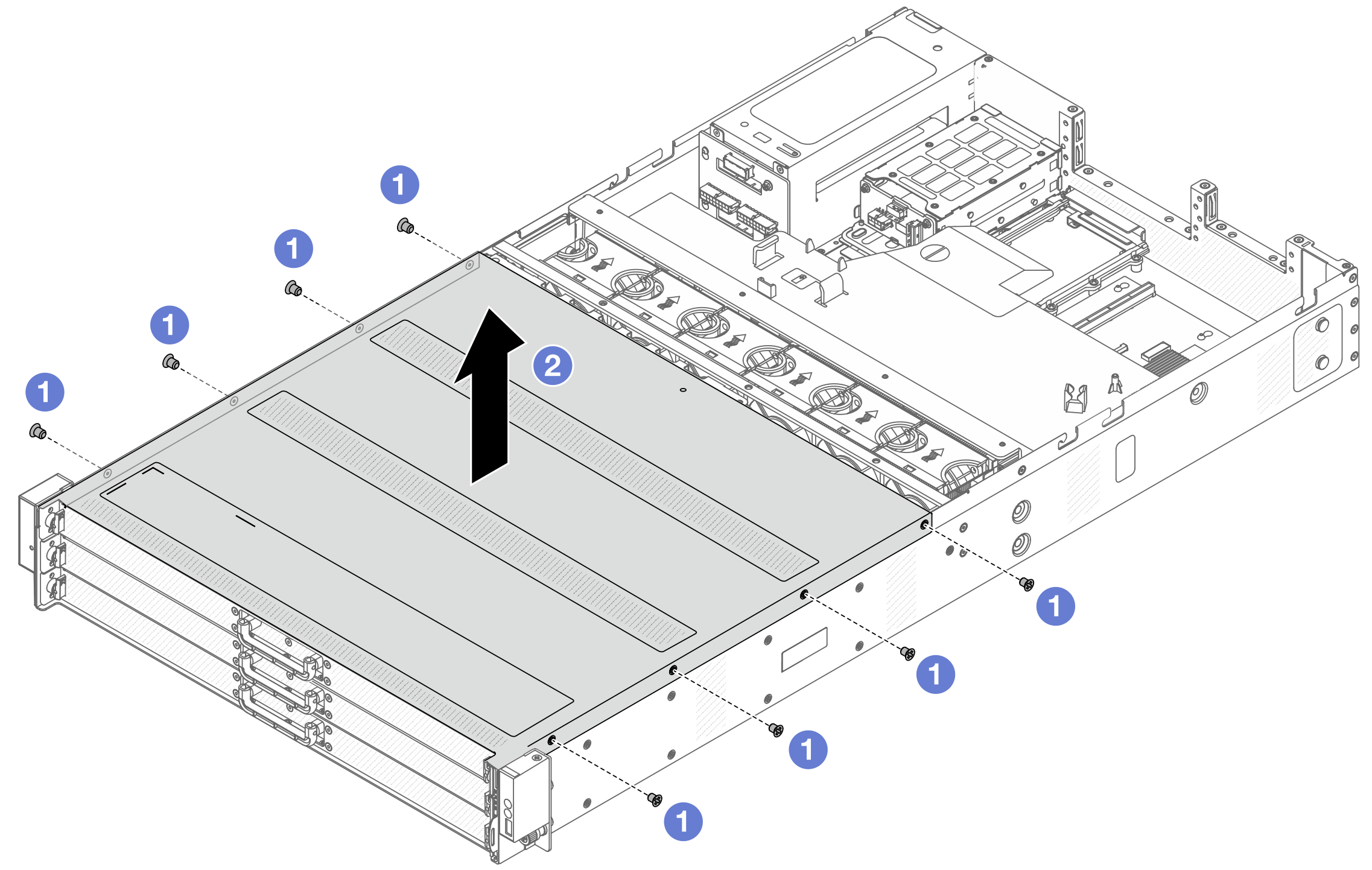
 Use a screwdriver to remove the screws that locks the front top cover.
 Lift the front cover up and remove it.
- Pull out the front drive trays steadily to get access to top and middle CMAs.Figure 2. Extending top, middle and bottom CMAs
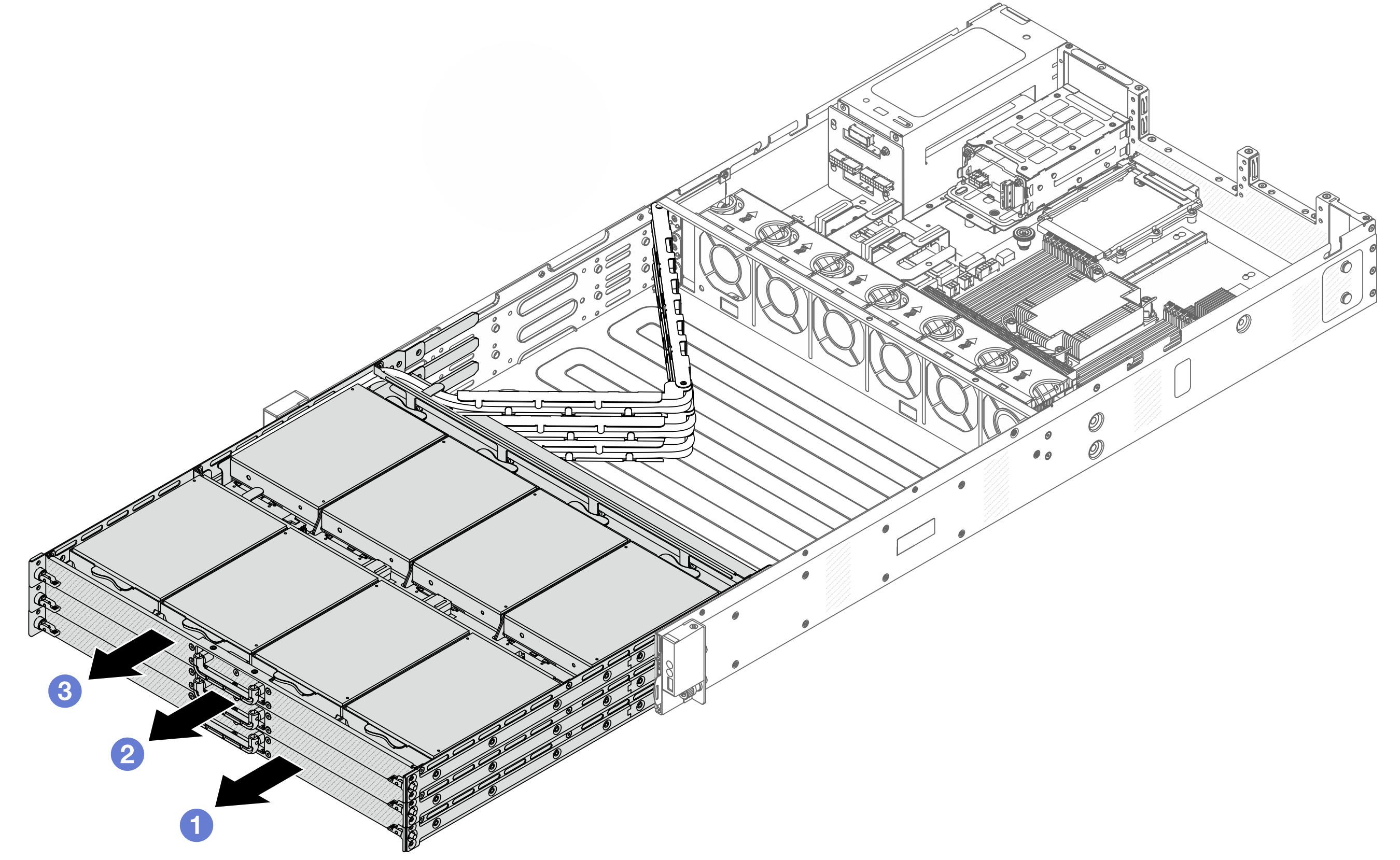
- Pull out bottom CMA first.
- Pull out middle CMA next.
- Pull out top CMA.
- Remove top CMA with cables attached.Figure 3. Removing top CMA
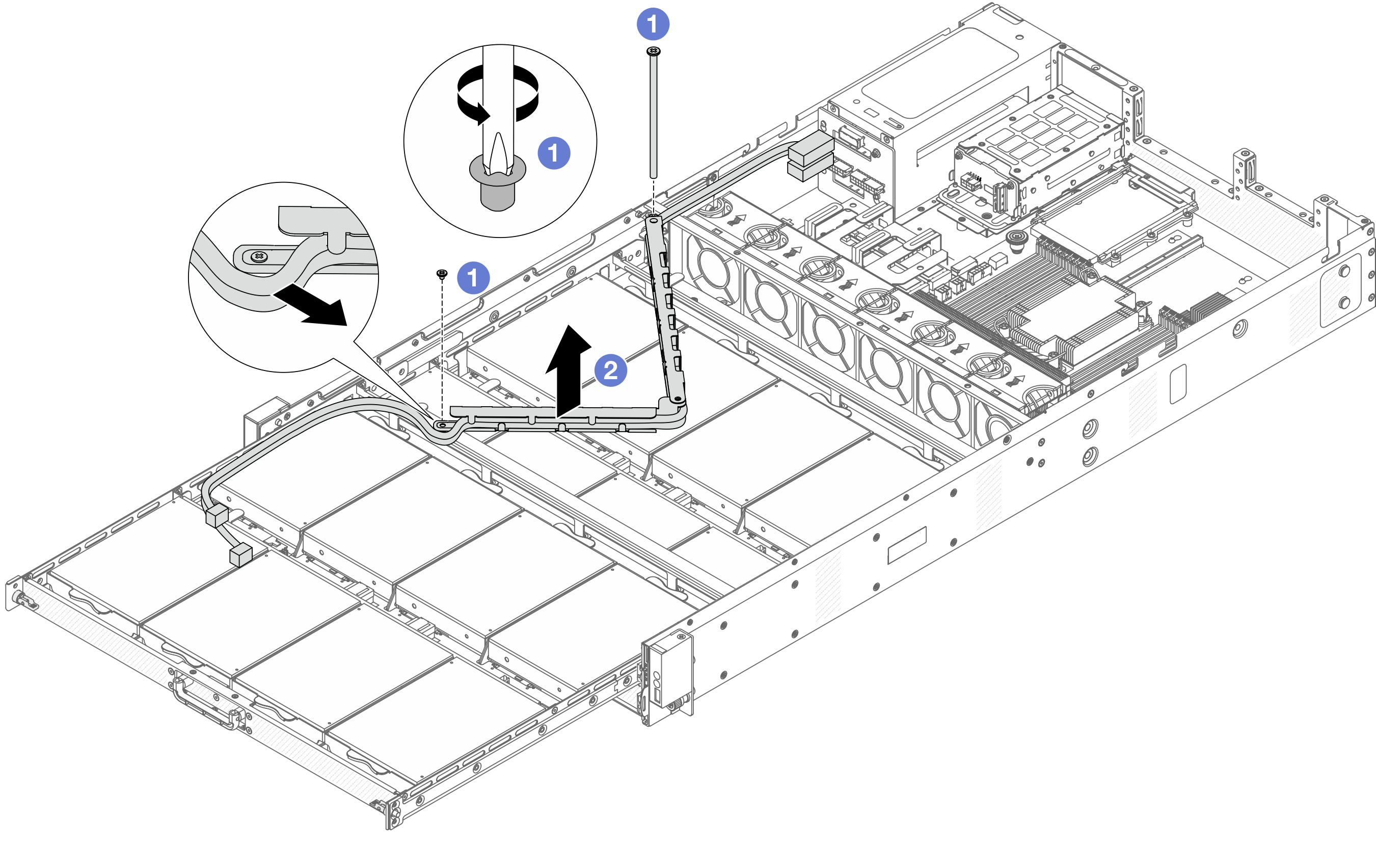
- Use a screwdriver to remove the screws that lock top CMA.
- Lift the top CMA and remove it.
- Remove the top drive tray to gain access to middle CMA.Figure 4. Removing top drive tray
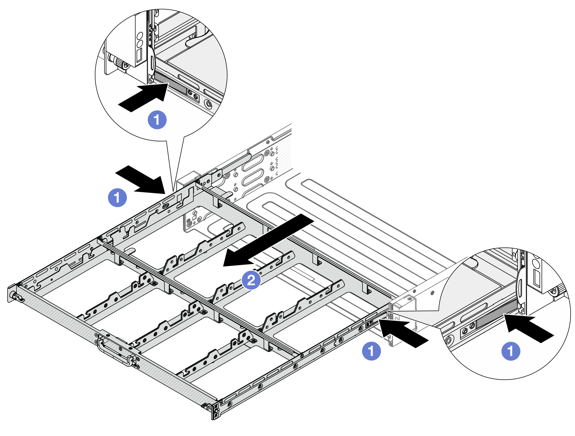
- Press the latches on both sides to unlock the tray.
- Pull out the top tray.
- Remove middle CMA with cables attached.Figure 5. Removing middle CMA
- Use a screwdriver to remove the screw that locks the middle CMA.
- Lift the middle CMA and remove it.
- Remove the middle drive tray to gain access to bottom CMA.Figure 6. Removing middle drive tray
- Press the latches on both sides to unlock the tray.
- Pull out the middle tray.
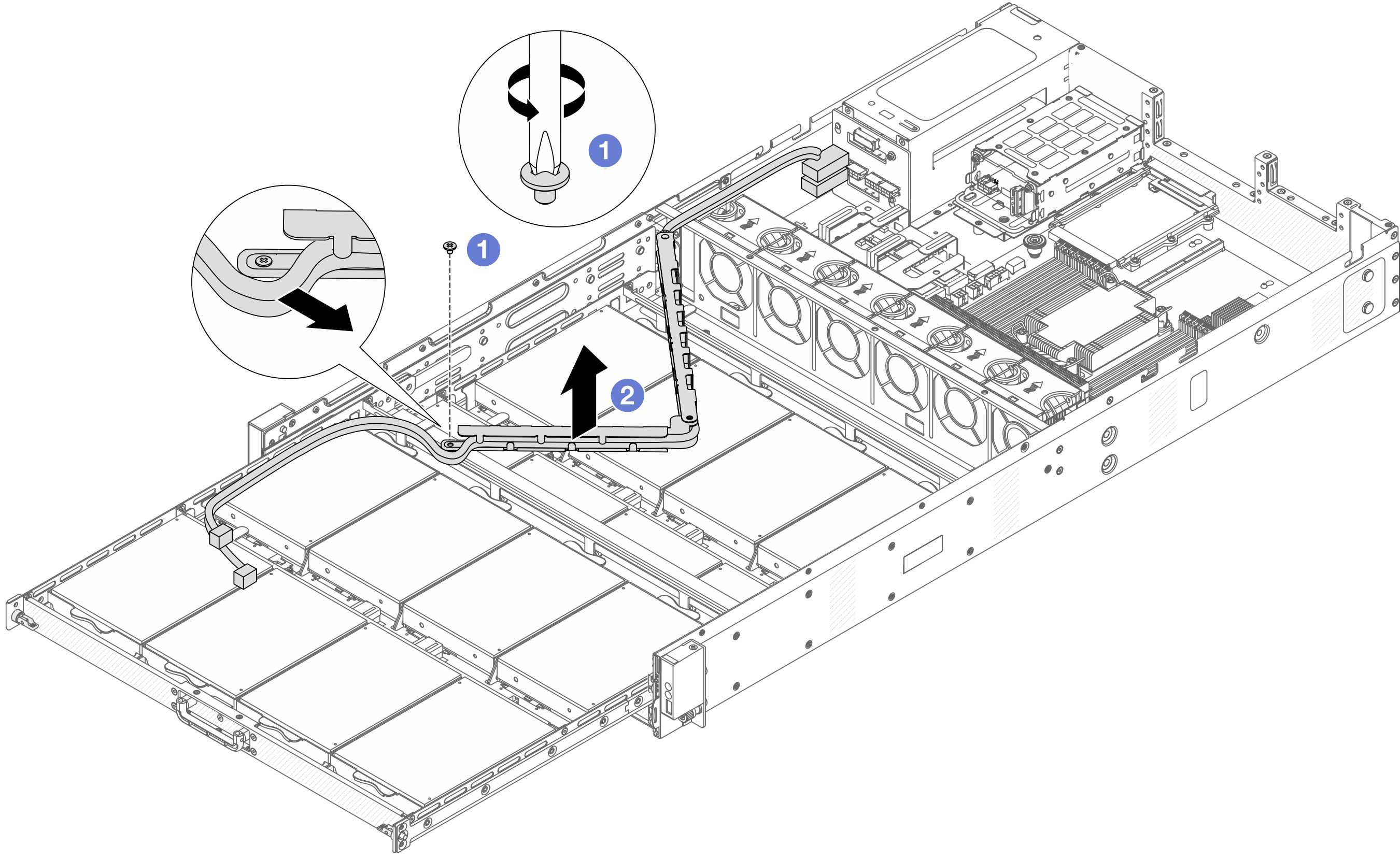
- Remove the bottom CMA with cables attached.Figure 7. Removing bottom CMA
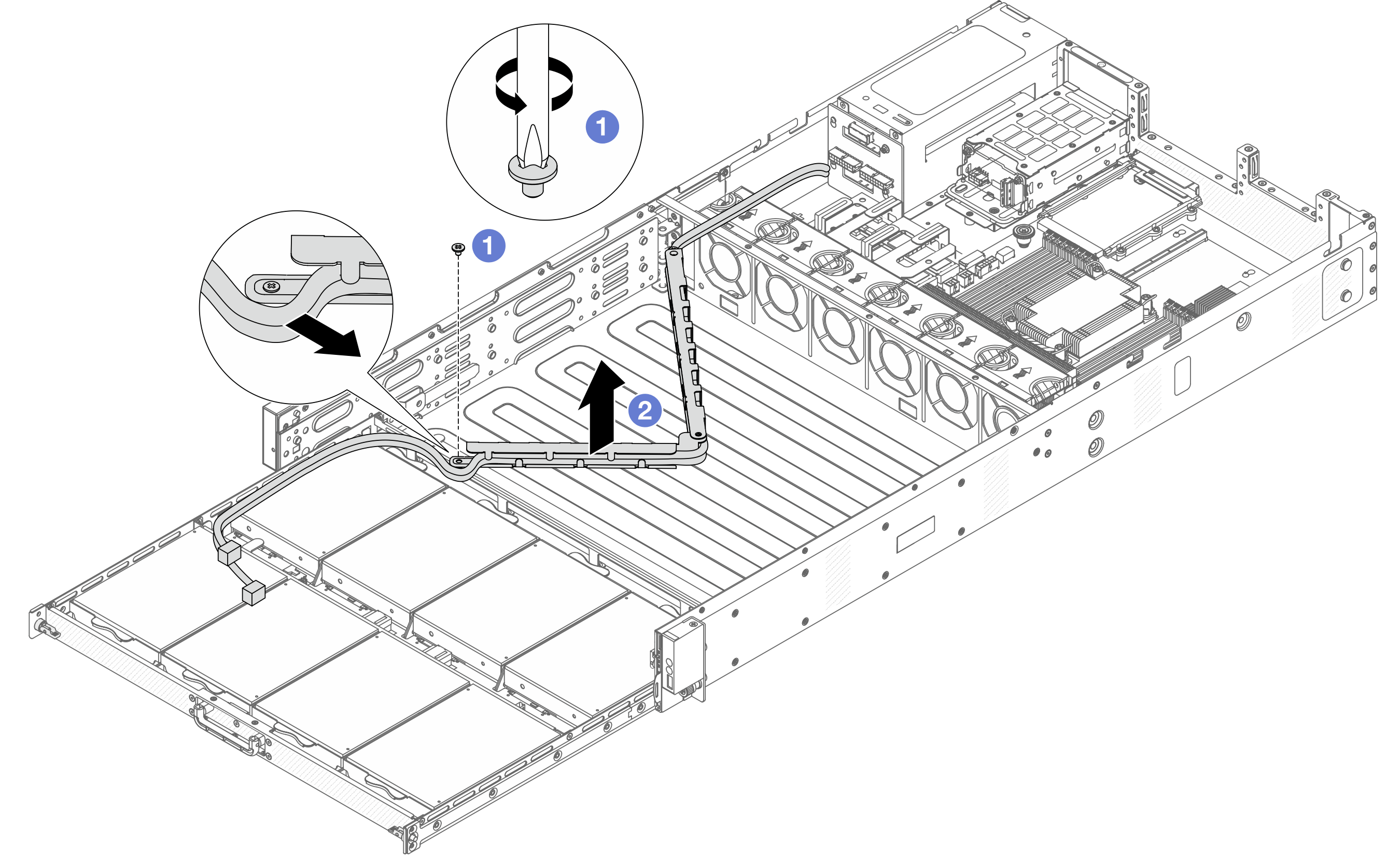
- Use a screwdriver to remove the screw that locks the bottom CMA.
- Lift the bottom CMA and remove it.
After you finish
If you are instructed to return the component or optional device, follow all packaging instructions, and use any packaging materials for shipping that are supplied to you.
Demo video