Install bottom cable management arm (CMA)
Follow instructions in this section to install the bottom cable management arm (CMA).
About this task

Hazardous energy present. Voltages with hazardous energy might cause heating when shorted with metal, which might result in spattered metal, burns, or both.

Read Installation Guidelines and Safety inspection checklist to ensure that you work safely.
Power off the server and peripheral devices and disconnect the power cords and all external cables. See Power off the server.
Prevent exposure to static electricity, which might lead to system halt and loss of data, by keeping static-sensitive components in their static-protective packages until installation, and handling these devices with an electrostatic-discharge wrist strap or other grounding systems.
Procedure
- Install the bottom CMA.Figure 1. Installing bottom CMA
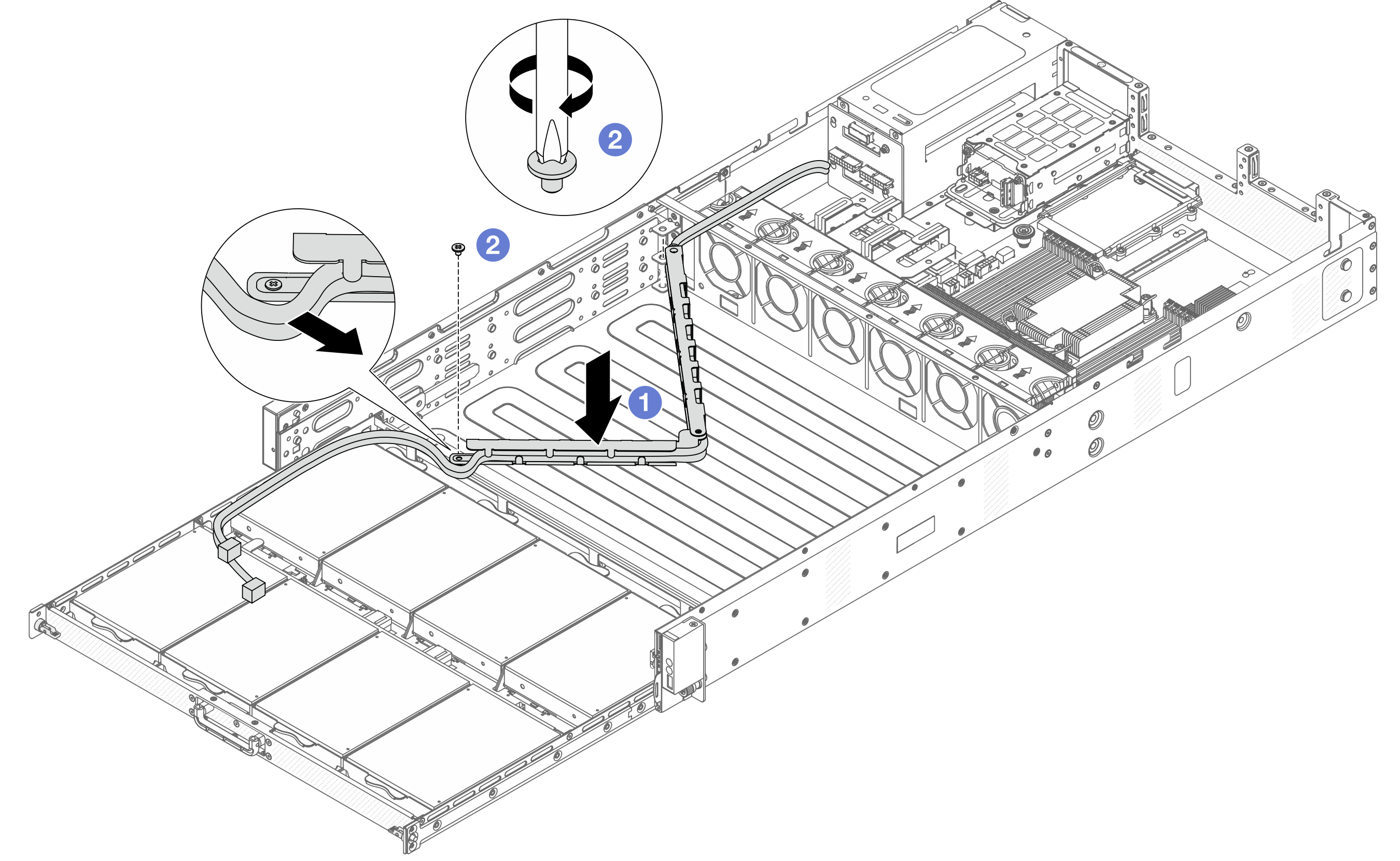
 Lower the bottom CMA into the chassis until both sides align the screw holes on the chassis.
 Use a screwdriver to install the screws to secure the bottom CMA.
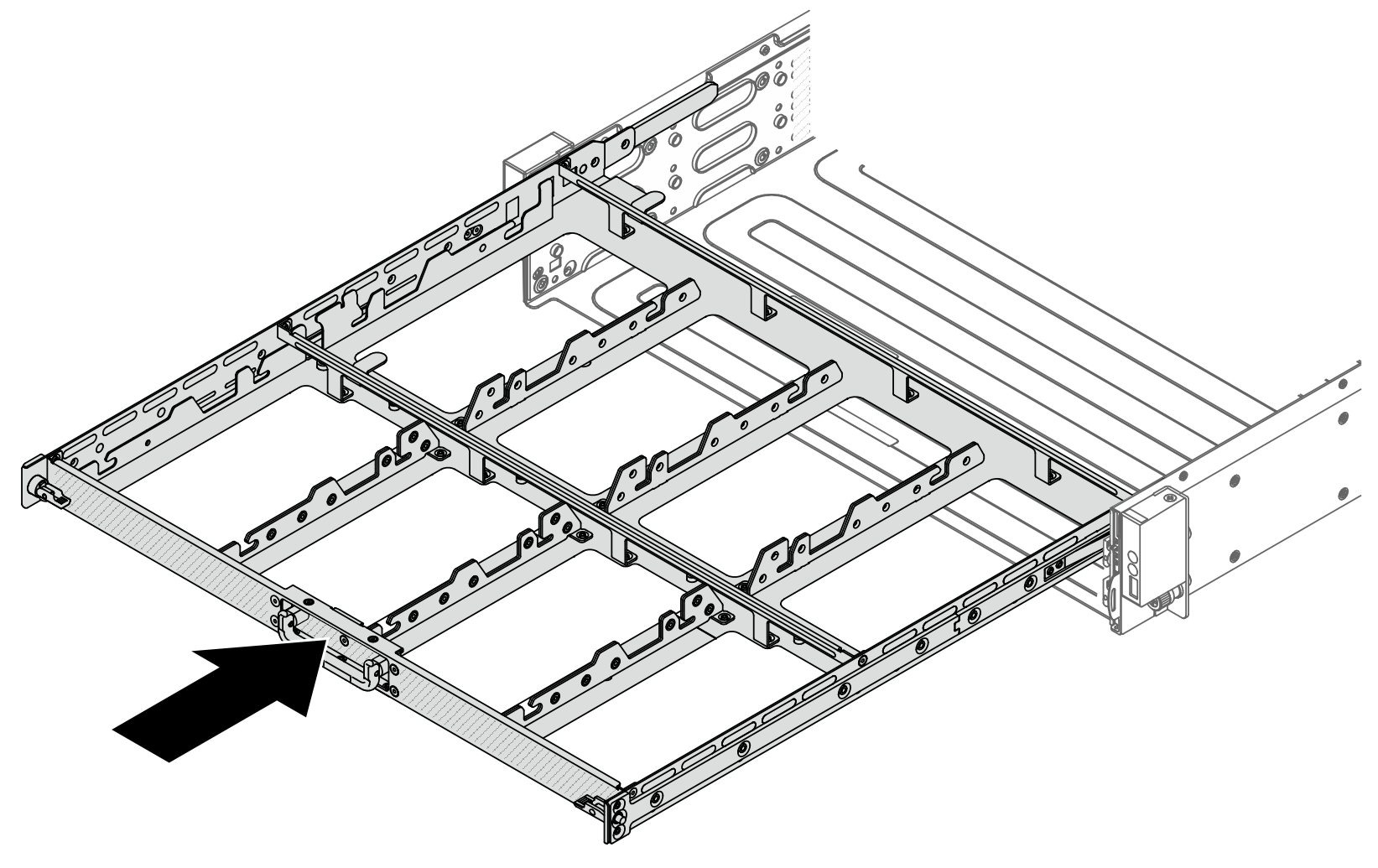
- Install middle drive tray. Align the latches on both sides of the tray with chassis, and push it into the rails steadily.Figure 2. Installing middle tray
- Install the middle CMA.Figure 3. Installing middle CMA
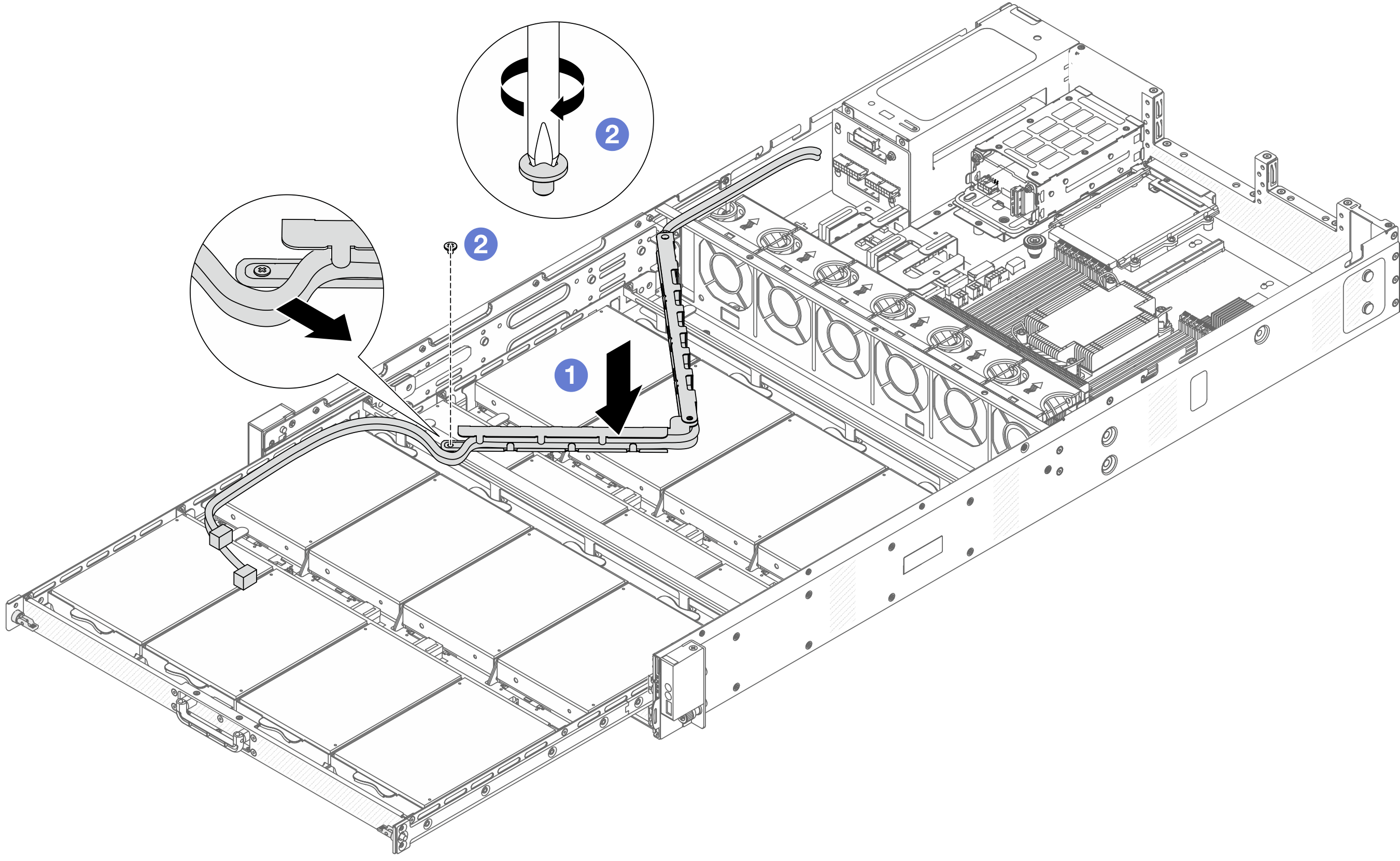
- Lower the middle CMA into the chassis until both sides align the screw holes on the chassis.
- Use a screwdriver to install the screws to secure the middle CMA.
- Install top drive tray. Align the latches on both sides of the tray with chassis, and push it into the rails.Figure 4. Installing top tray
- Install the top CMA.Figure 5. Installing the top CMA
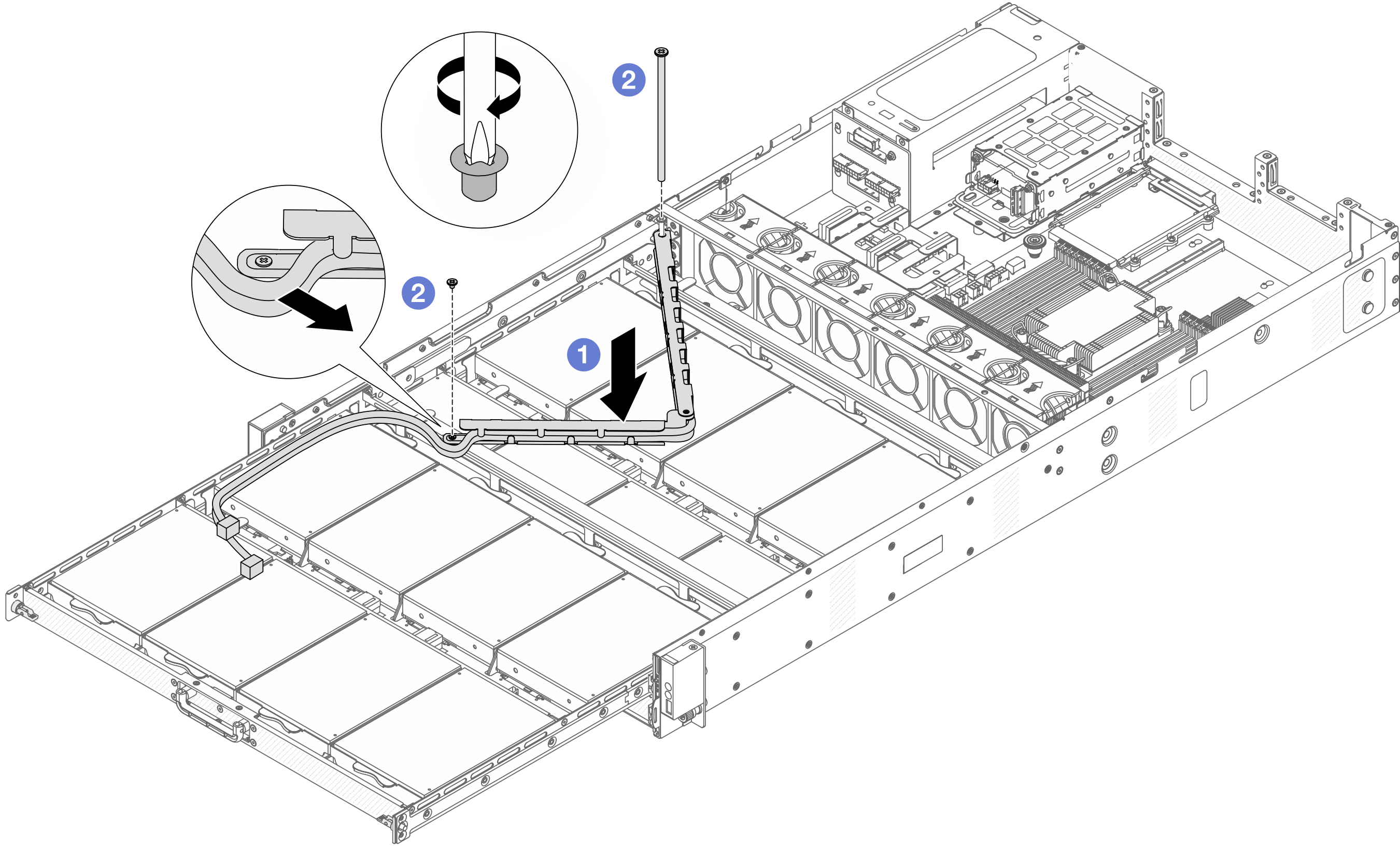
- Lower the top CMA into the chassis until both sides align the screw holes on the chassis.
- Use a screwdriver to install the screws to secure the top CMA.
- Push the front drive trays back into position.Figure 6. Folding top, middle and bottom CMAs
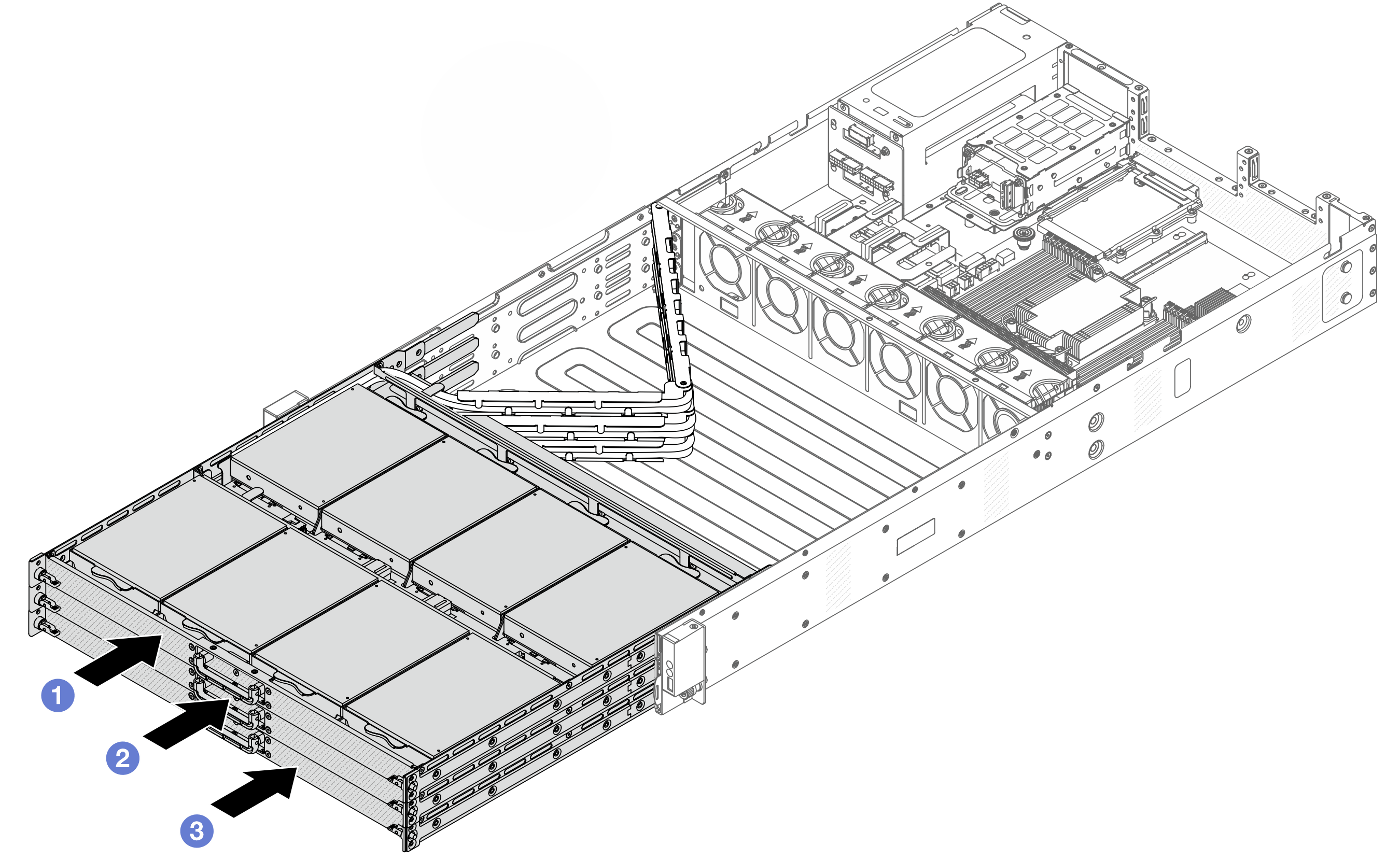
- Push the top drive tray back first.
- Push in the middle drive tray next.
- Push in the bottom drive tray.
- Install the front top cover to the server.Figure 7. Front top cover installation
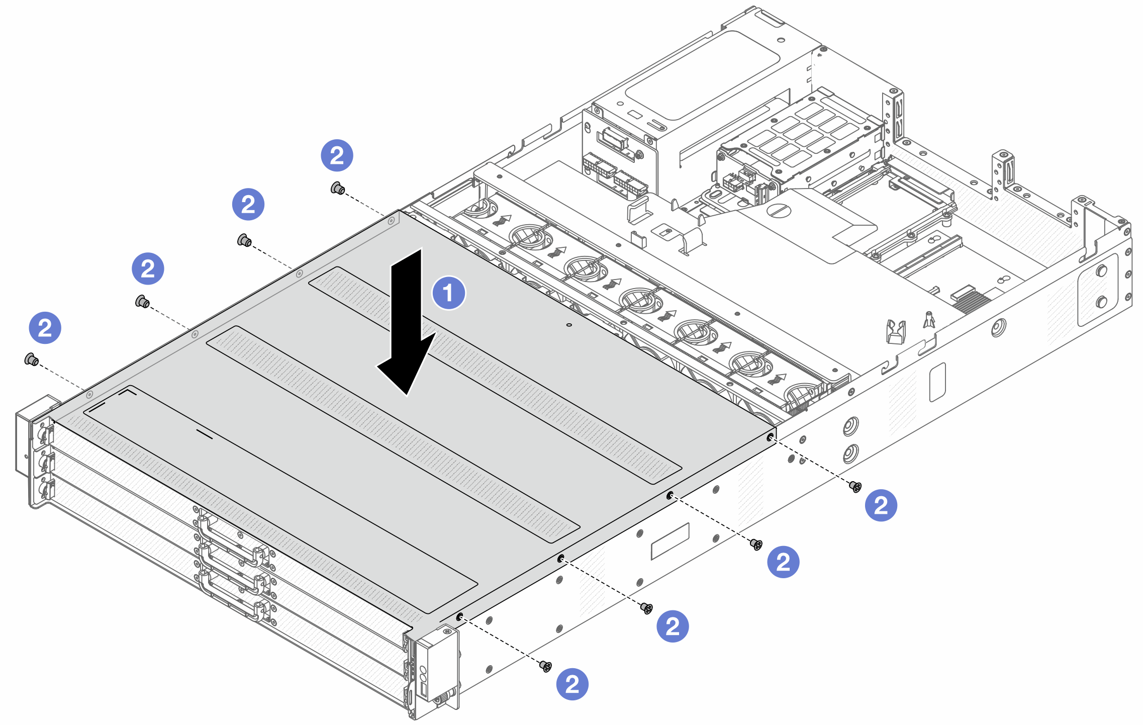
- Lower the front top cover onto the chassis until both sides of the top cover engage the guides on both sides of the chassis.
- Use a screwdriver to install the screws to secure the front top cover.
After you finish
After installing the top cover, complete the parts replacement. See Complete the parts replacement.
Demo video