When you create and deploy a server pattern to support booting a system from SAN, ensure that you identify the SAN boot target and the adapters that are part of the server.
Procedure
To create and deploy a server pattern that supports the deployment of the operating system on SAN storage, complete the following steps.
- From the Lenovo XClarity Administrator menu bar, click . The Configuration Patterns: Patterns page is displayed.
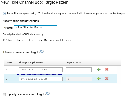
- To identify the WWPN and LUN IDs of the storage volumes where the operating system is to be deployed, create a category pattern.
- Click the Category Patterns tab.
- Click Fibre Channel Boot Target Patterns, and then click the Create icon (
 ).
). - Enter the WWPN of the storage target.
Click Allow Multiple LUN Identifiers to assign multiple target LUN identifiers to the same storage volumes.

- Click Create to create the pattern. The target is displayed in the list of Fibre Channel boot target patterns.
- Click the Server Patterns tab to create a pattern.
- Click the Create icon (
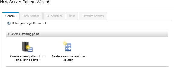
 ). The New Server Patterns Wizard is displayed.
 - Click Create a new pattern from scratch.
- On the General tab:
- Select Flex Compute Node for the form factor.
- Specify a pattern name (x240_san_boot) and description.
- Click Next.
- On the Local Storage tab, consider disabling the local storage adapter if you are using a diskless system to improve boot times that are related to scanning for local drives. Then, click Next.
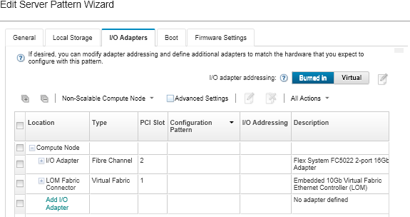
- On the I/O Adapters tab, add the Ethernet and Fibre Channel cards. Ensure that they are in the appropriate PCI slots.
- For each card, click Add I/O Adapter, choose the PCI slot where the card is located, and select the card.
Ensure that you specify an Ethernet card and a Fibre Channel card.

- Ensure that I/O adapter addressing is set to Virtual. Then click the Edit icon
 to specify the configuration to be used for Ethernet (MAC) virtual addressing and Fibre Channel (WWN) virtual addressing.
From the page, you can choose to use the burned-in MAC address for the Ethernet card by disabling the virtual addressing. However, to select and use a Fibre Channel boot-target pattern, you must use virtual addressing for the Fibre Channel adapter.
- Click Next.
- On the Boot tab, add the SAN boot target pattern that you created earlier.
- On the SAN Boot tab, choose the boot target pattern that you defined.
- Click Next.
- On the Firmware Settings tab, define any additional category patterns that are to be included in this server pattern. You can define the following category patterns.
- Click Save and Deploy to save the pattern to Lenovo XClarity Administrator, and deploy it to the servers on which you intend to install VMware ESXi.
After you finish
Consider the following steps after the server pattern has been deployed to all servers.
- Take the virtualized WWPN addresses that were created, and add them to the storage zone so that the server can reach the defined storage LUNs.
After you deploy the server profile, you can find the virtualized WWPN addresses by viewing the server profile.
- From the Lenovo XClarity Administrator menu bar, click .
- Click the deployed server profile (for example, x240_SAN_boot). The Virtual Address Mapping tab displays the list of addresses.
- Deploy the operating system to the server.


