Rear I/O and OCP module cable routing
Follow instructions in this section to install and route the cables for the rear I/O module and OCP module.
Note
Connections between connectors; 1↔1, 2↔2, 3↔3, ... n↔n
When routing the cables, make sure that all cables are routed appropriately through the corresponding cable guides and cable clips.
- Strictly observe the following instructions to avoid damaging cable sockets on the system board. Any damage to the cable sockets might require replacing the system board.
Connect cable connectors vertically or horizontally in alignment with the orientations of the corresponding cable sockets, avoiding any tilt.
- To disconnect cables from the system board, do as follows:
Press and hold all latches, release tabs, or locks on cable connectors to release the cable connectors.
- Remove the cable connectors vertically or horizontally in alignment with the orientations of the corresponding cable sockets, avoiding any tilt.NoteThe cable connectors might look different from those in the illustration, but the removal procedure is the same.
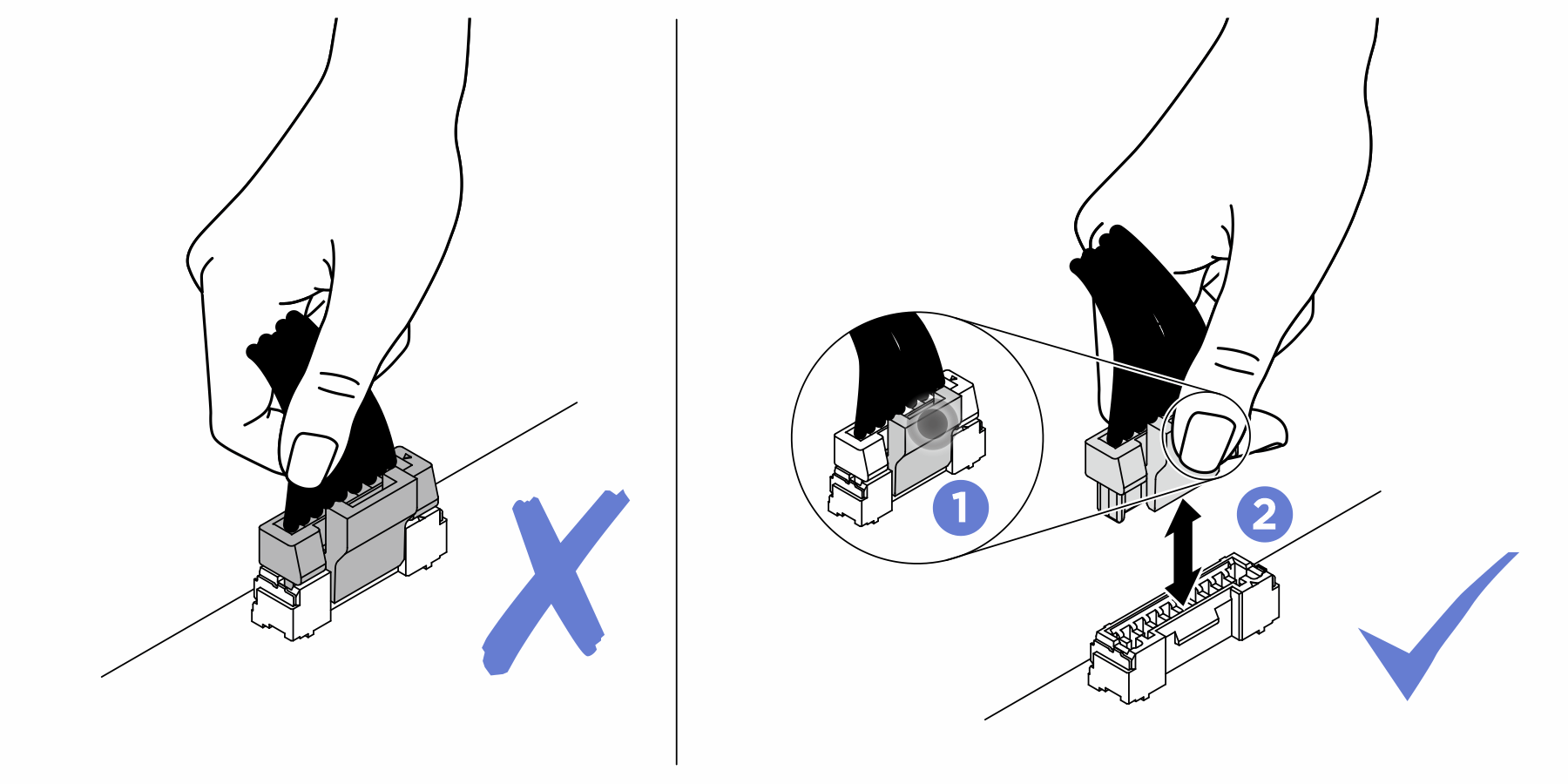
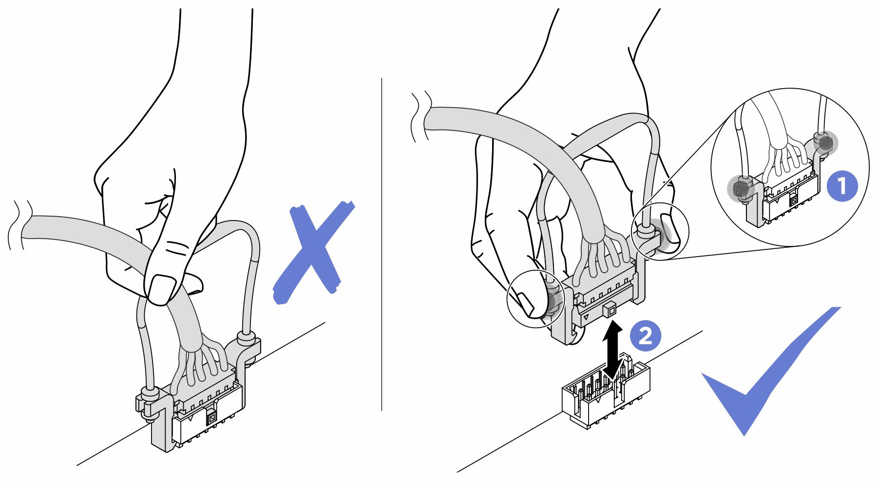
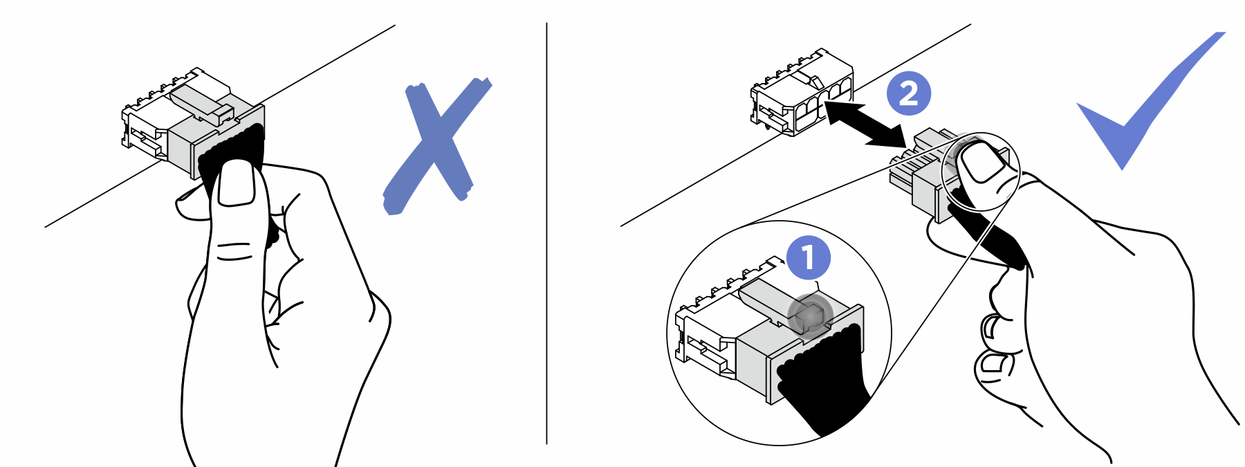
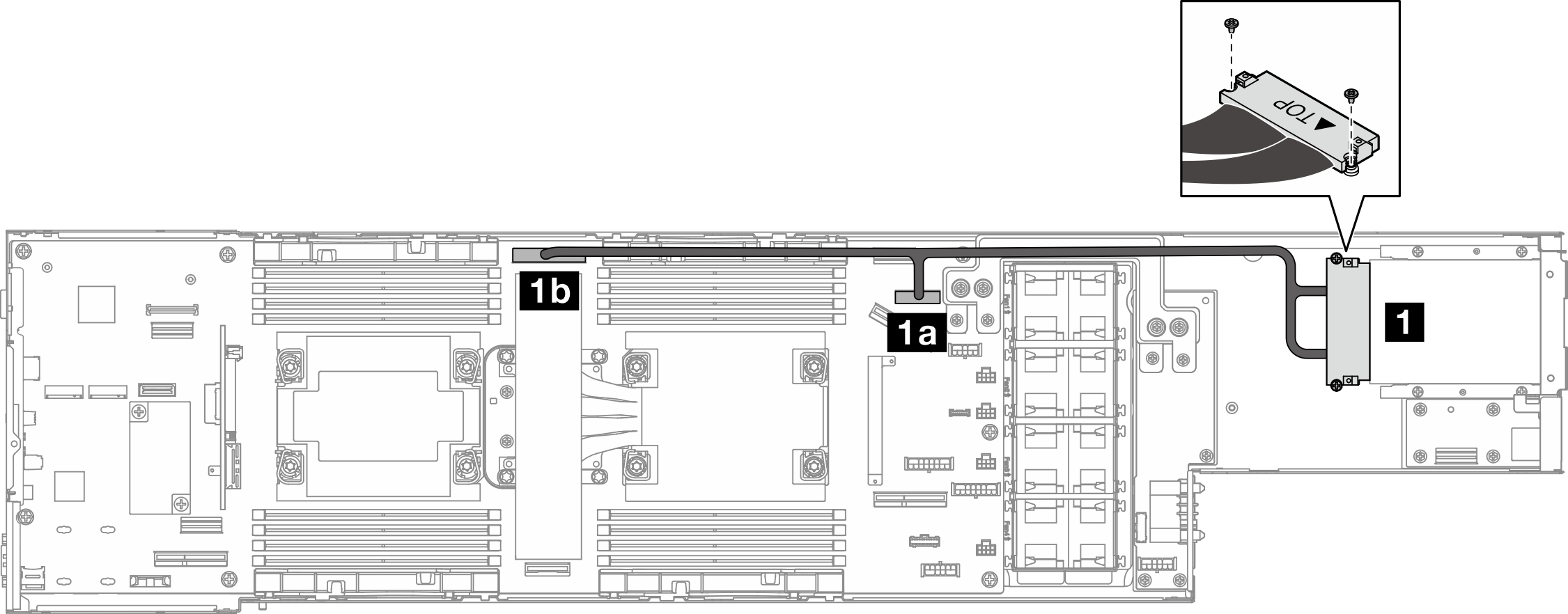
Figure 1. Cables for the rear I/O module and OCP module
| From | To (system board) | Cable |
|---|---|---|
| 1 Node bottom (secured with screws) | 1a OCP power and sideband connector | OCP connector to MCIO x8 (270 mm) |
| 1b OCP signal connector | OCP connector to MCIO x16 (450 mm) |
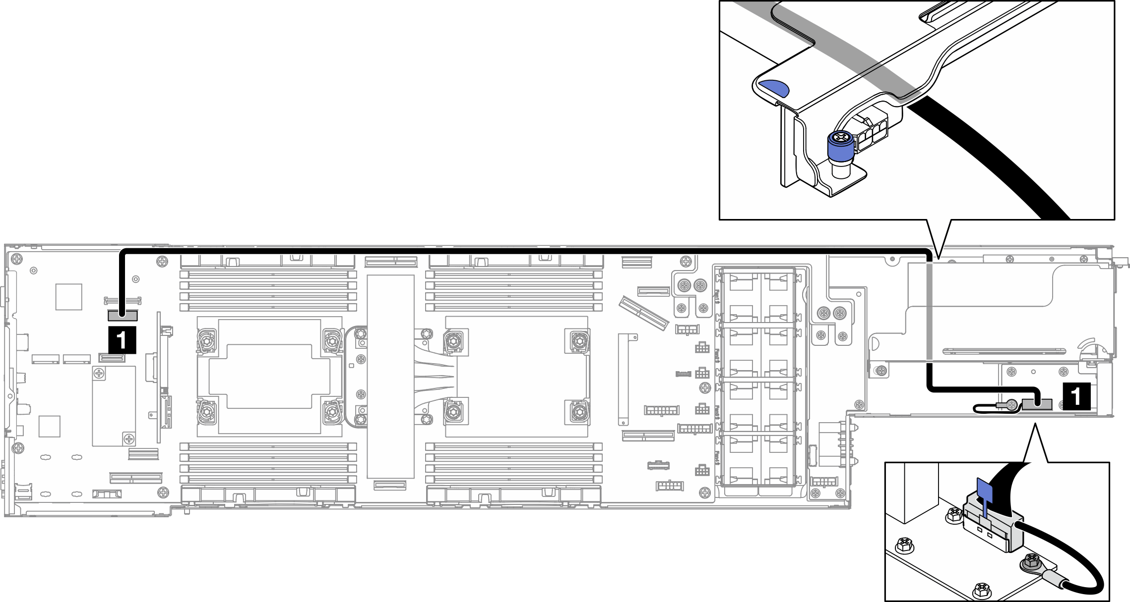
| From | To (system board) | Cable |
|---|---|---|
| 1 Rear I/O signal connector (on the rear I/O module) | 1 Rear I/O signal connector | Low-profile SlimSAS x8 to low-profile SlimSAS x8 (915 mm) |
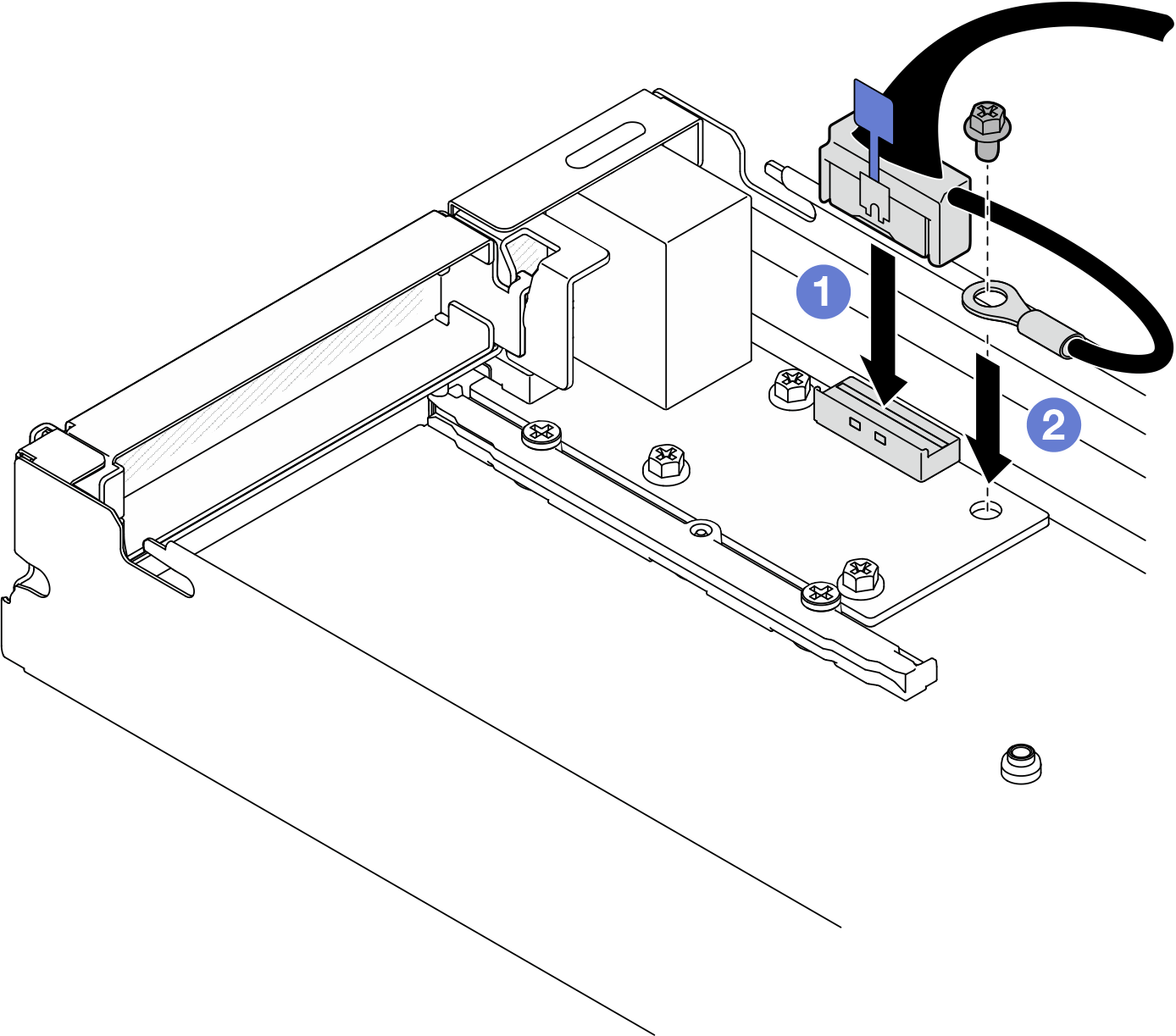
Note
When connecting the rear I/O cable to the rear I/O module, make sure to secure the attached grounding cable with a screw.
Figure 2. Installation of the rear I/O cable and grounding cable
Give documentation feedback