Remove a node from the chassis
Follow instructions in this section to remove a node from the chassis.
About this task
To avoid potential danger, make sure to read and follow the safety information.
R006

CAUTION
Do not place any object on top of a rack-mounted device unless that rack-mounted device is intended for use as a shelf.
Attention
- Read Installation Guidelines and Safety inspection checklist to make sure that you work safely.
- When removing the node, note the node tray number and make sure to install the node in the same tray from which it was removed. Reinstalling the node into a different tray requires the node to be reconfigured.
- Be careful when removing or installing the node to avoid damaging the node connectors.
- For proper cooling, each node tray must be installed with either a node or node tray fillers before the nodes in the chassis are powered on.
Note
Depending on the specific configuration, the hardware might look slightly different from the illustrations in this section.
Procedure
- Make preparations for this task.
- Power off the node (see Power off the node); then, disconnect all external cables from the node.
- Remove the node from the chassis.
 Pivot and release the front handle of the node.
 Carefully slide the node out of the chassis until you see the warning icon on the side label of the node. Then, hold the node with both hands as illustrated and carefully pull it out of the chassis.AttentionFor safety, make sure to hold the node with both hands when lifting the node.Figure 1. Node removal from a left tray
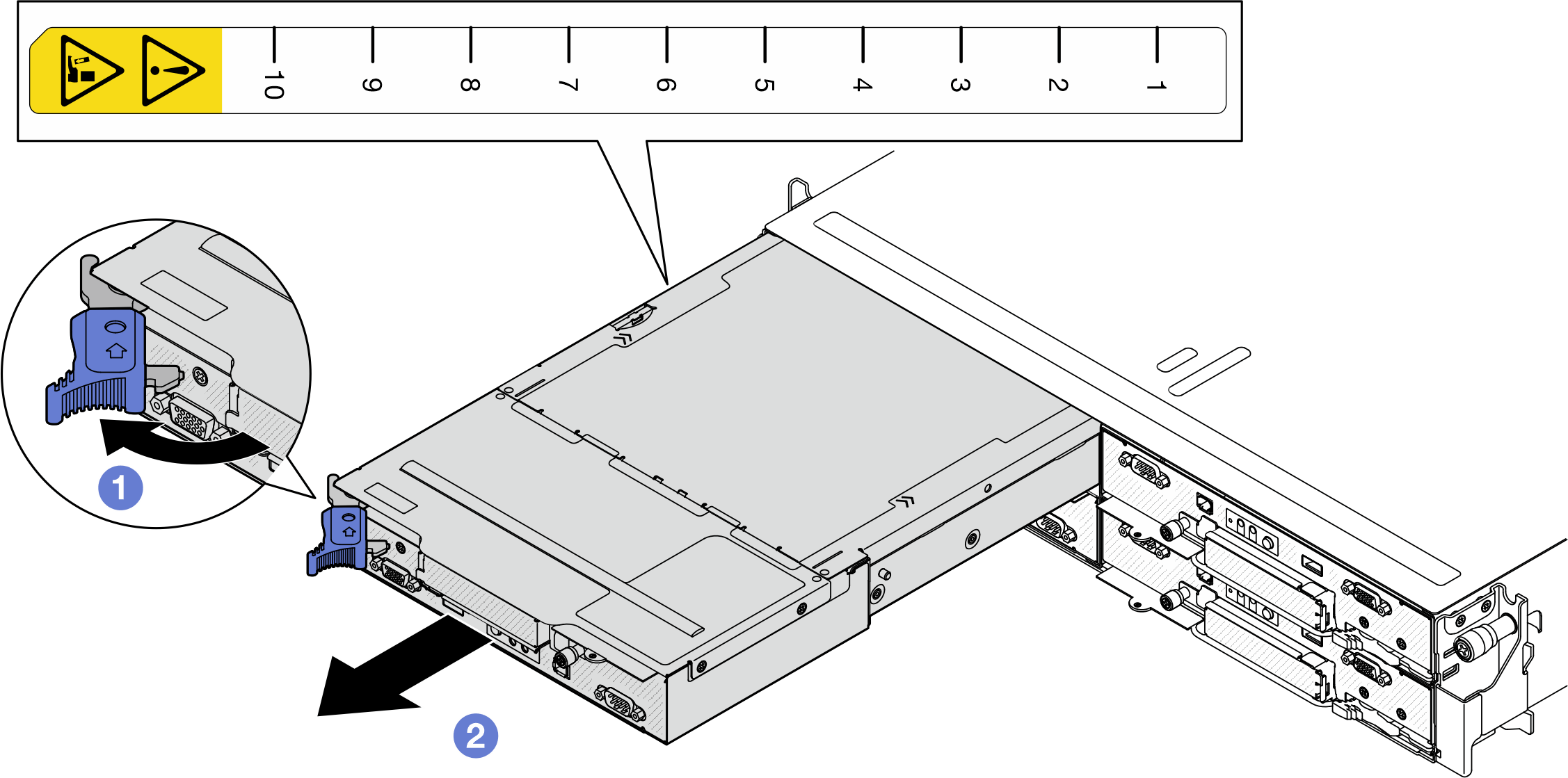 Figure 2. Node removal from a right tray
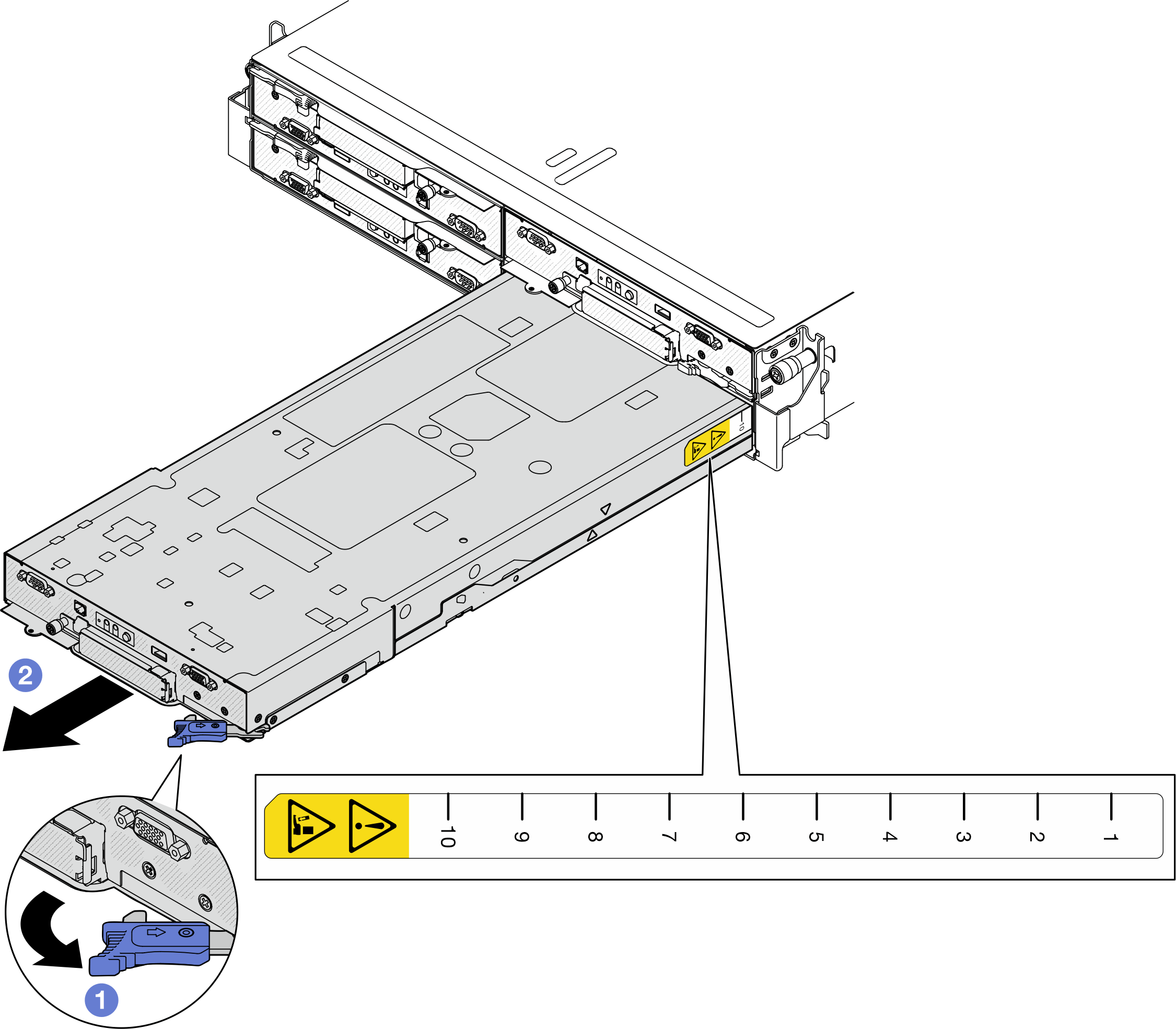
After you finish
- Install either a replacement node (see Install a node to the chassis) or front and rear node tray fillers into the node tray within one minute.ImportantFor proper cooling, each node tray must be installed with either a node or node tray fillers before the nodes in the chassis are powered on.Figure 3. Installation of a front node tray filler
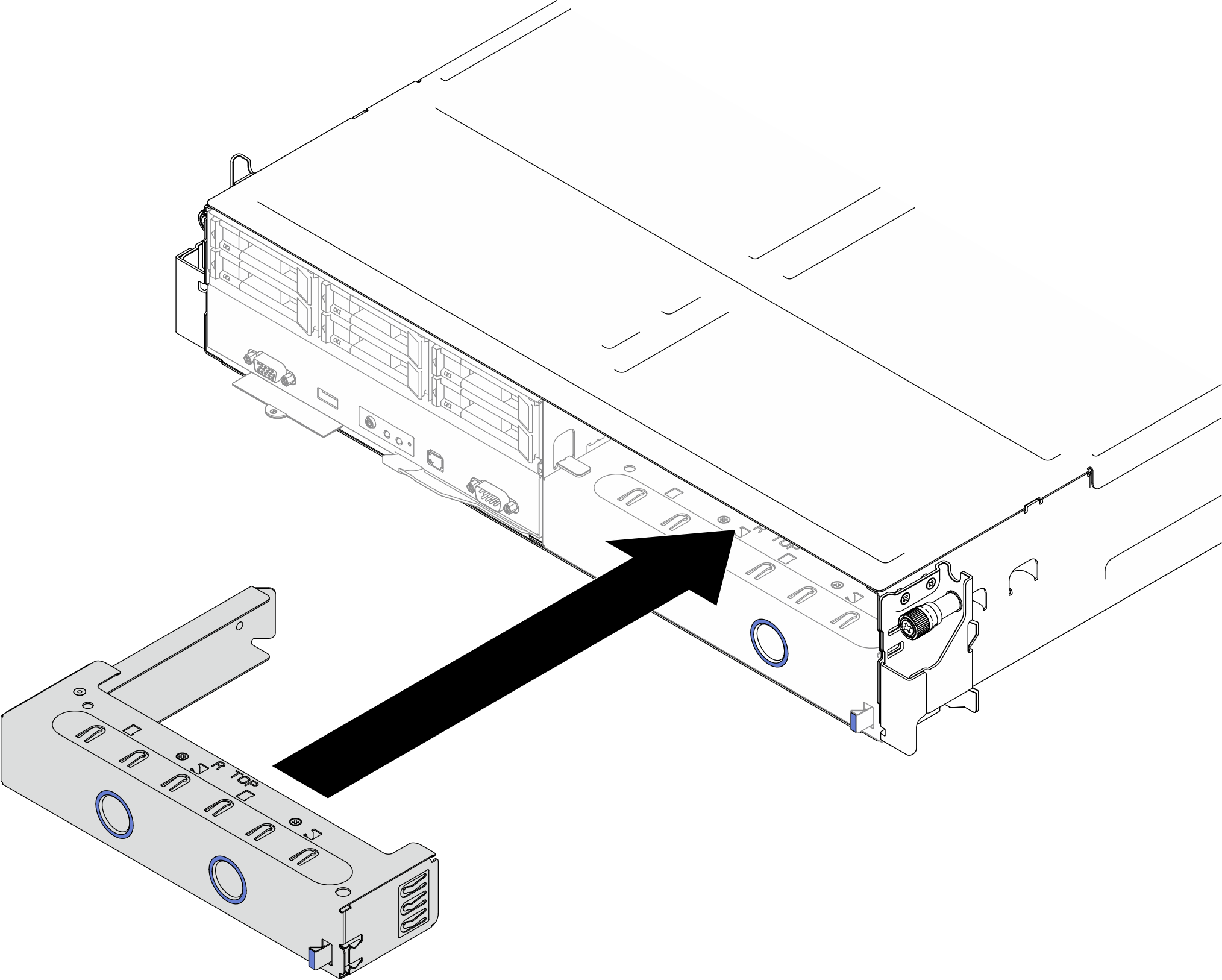 Figure 4. Installation of a rear node tray filler
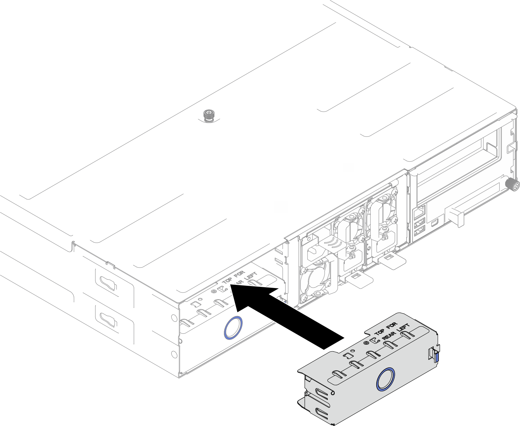
- If you are instructed to return the component or optional device, follow all packaging instructions, and use any packaging materials for shipping that are supplied to you.
Demo video
Give documentation feedback