Install the bus bar
Use this information to install the bus bar.
About this task
Read Installation Guidelines and Safety inspection checklist to ensure that you work safely.
Turn off the corresponding DWC tray that you are going to perform the task on.
Disconnect all external cables from the enclosure.
Use extra force to disconnect QSFP cables if they are connected to the solution.
To avoid damaging the water loop, always use the water loop carrier when removing, installing or folding the water loop.
- A video of this procedure is available at YouTube.
Procedure
- Make sure that the carrier board power cable and the MCIO cable are routed properly.
- Make sure the two cables are clear off the middle part of the bus bar. There should not be any cables between the bus bar and the GPU board.
- Make sure the two cables are routed underneath the rear end of the bus bar.
Figure 1. Routing carrier board power cable and MCIO 1 cable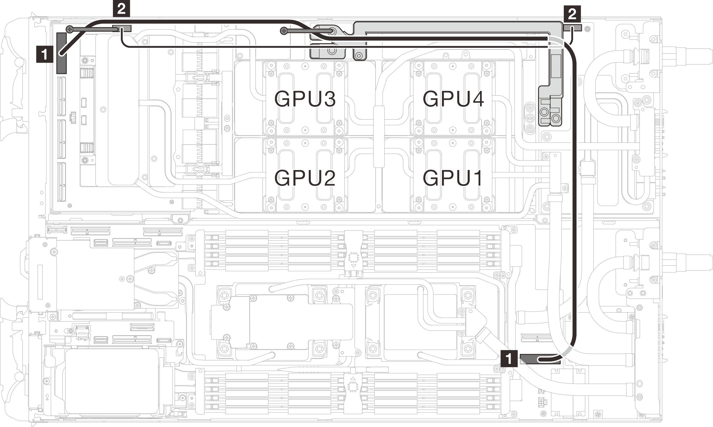
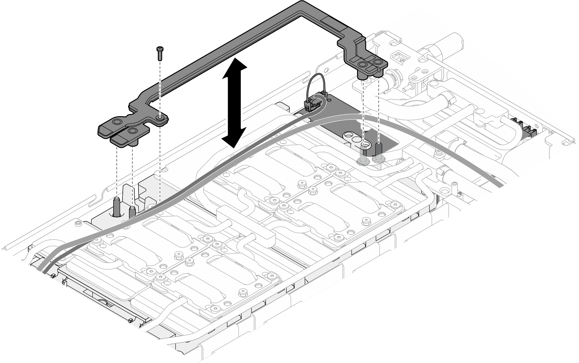
From (carrier board) To 1 MCIO 1 1 PCIe x 16 MCIO 3 connector 2 Power and side band connector 2 Power connector (on GPU power distribution board) - Align the bus bar with the guide pins on the GPU board while placing it to the GPU board. Then, fasten the screw to secure the bus bar to the GPU board.Figure 2. Bus bar installation
Install the cross braces. See Install the cross braces.
Install the tray cover. See Install the tray cover.
Install the tray into the enclosure. See Install a DWC tray in the enclosure.
- Connect all required external cables to the solution.NoteUse extra force to connect QSFP cables to the solution.
Check the power LED on each node to make sure it changes from fast blink to slow blink to indicate all nodes are ready to be powered on.