Install a processor
This task has instructions for installing a processor. This task requires a Torx T30 driver.
About this task
- Read the following sections to ensure that you work safely.
- Turn off the corresponding DWC tray that you are going to perform the task on.NoteIf Shared I/O adapters are installed, power off the auxiliary node (node 1/3/5/7/9/11) first, and then power off the primary node (node 2/4/6/8/10/12).
- Disconnect all external cables from the enclosure.NoteUse extra forces to disconnect QSFP cables if they are connected to the solution.
If the Intel® Xeon® Platinum 8368Q processor is installed, the supported water temperature is 2°C - 35°C (35.6°F - 95°F).
Each processor socket must always contain a cover. When removing or installing a processor, protect empty processor sockets with a cover.
Do not touch the processor socket or processor contacts. Processor-socket contacts are very fragile and easily damaged. Contaminants on the processor contacts, such as oil from your skin, can cause connection failures.
Do not allow the thermal grease on the processor or water loop to come in contact with anything. Contact with any surface can compromise the thermal grease, rendering it ineffective. Thermal grease can damage components, such as electrical connectors in the processor socket. Do not remove the grease cover from the cold plate until you are instructed to do so.
To avoid damaging the water loop, always use the water loop carrier when removing, installing or folding the water loop.
Before you install a new or replace a processor, update your system firmware to the latest level. See Update the firmware.
To avoid damaging the water loop, always use the water loop carrier when removing, installing or folding the water loop.
See Lenovo ServerProven website for a list of processors supported for your system. All processors on the system board must have the same speed, number of cores, and frequency.
Optional devices available for your system might have specific processor requirements. See the documentation that comes with the optional device for information.
Ensure you have “SD650 V2 or SD650-N V2 Neptune® DWC Waterloop Service Kit “ in hand to install components.
| Screwdriver Type | Screw Type |
| Torx T10 head screwdriver | Torx T10 screw |
| Torx T30 head screwdriver | Torx T30 screw |
| Phillips #1 head screwdriver or 3/16" hex head screwdriver | Phillips #1 screw |
| Phillips #2 head screwdriver | Phillips #2 screw |
Procedure
- Follow the following steps if you are replacing processors:
- Apply approximately 0.65 g of the new thermal grease to the center of the processor top. If you have cleaned the top of the processor with an alcohol cleaning pad, make sure to apply the new thermal grease after the alcohol has fully evaporated.Note
Carefully place the processor and retainer on a flat surface with the processor-contact side down.
Figure 2. Thermal grease application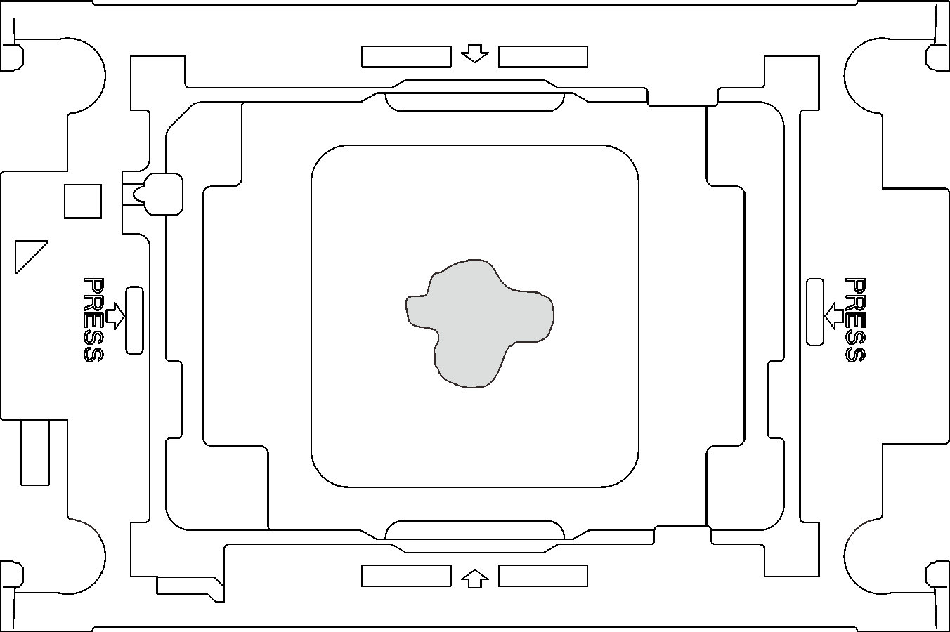
- Apply approximately 0.65 g of the new thermal grease to the center of the processor top. If you have cleaned the top of the processor with an alcohol cleaning pad, make sure to apply the new thermal grease after the alcohol has fully evaporated.
- Install processor retainers onto processors if needed.
- Gently place the processor retainer on the processor; then, carefully press the four sides of the processor retainer to secure the processor.Figure 3. Installing a processor retainer
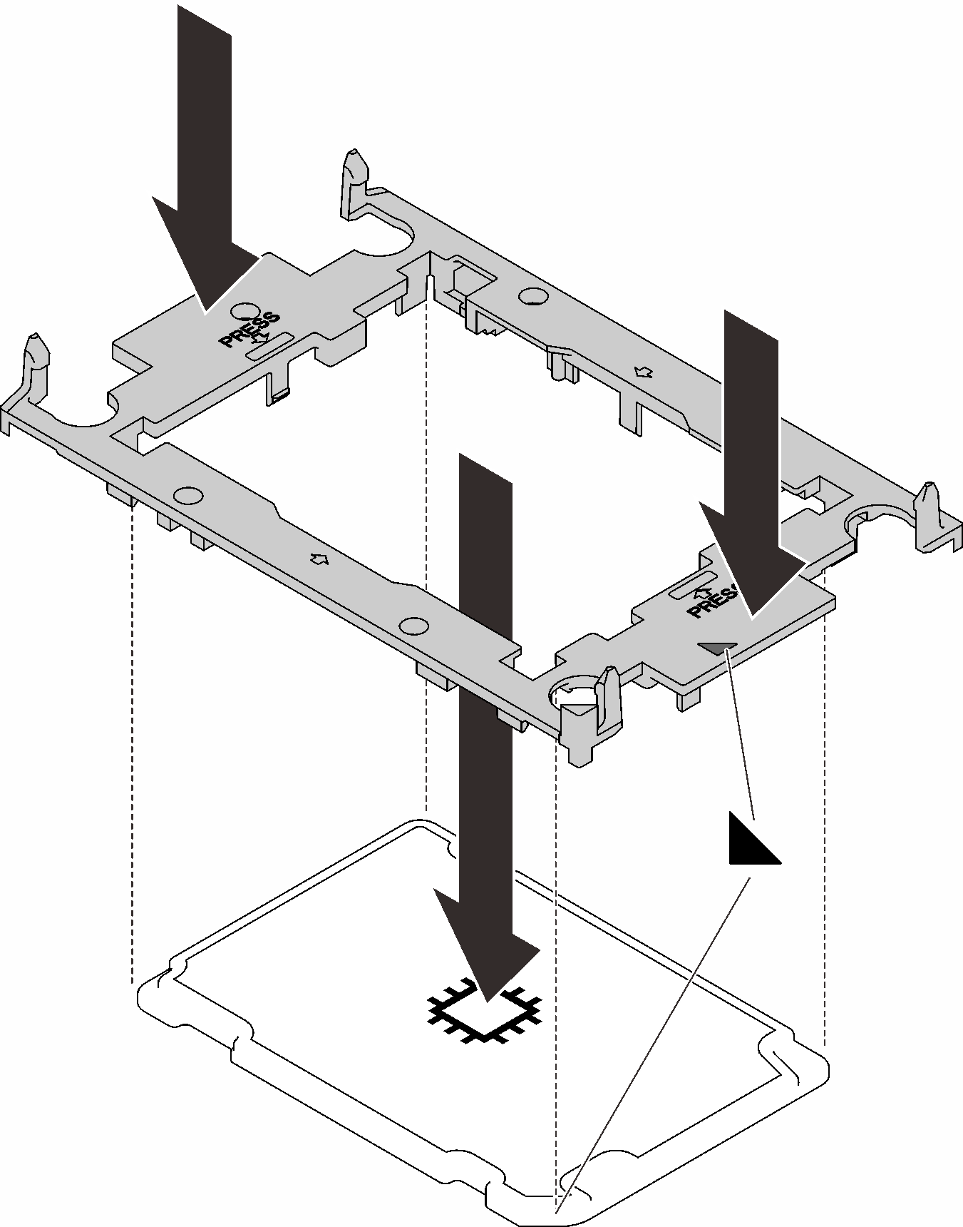
- Gently place the processor retainer on the processor; then, carefully press the four sides of the processor retainer to secure the processor.
- Remove two plastic grease covers if needed.
- ❶ Use a scissors to cut off tapes.
- ❷ Remove plastic grease covers from underside of water loop cold plates.
Figure 4. Plastic grease covers removal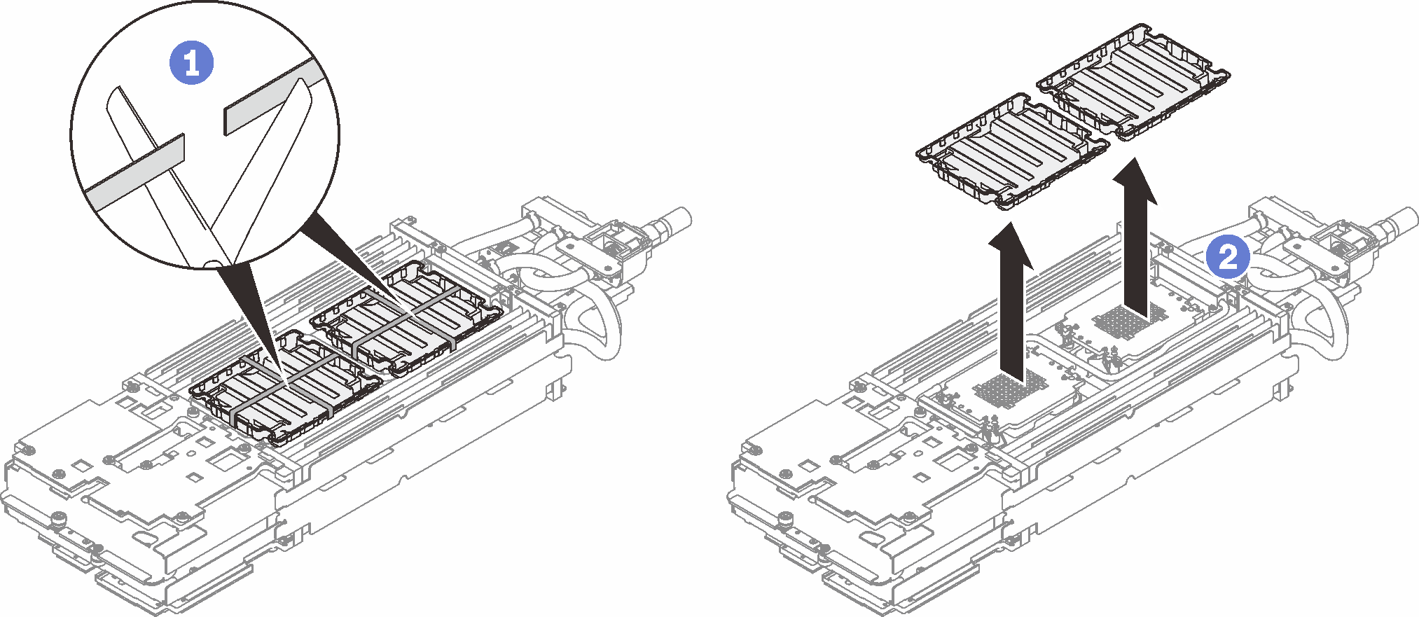
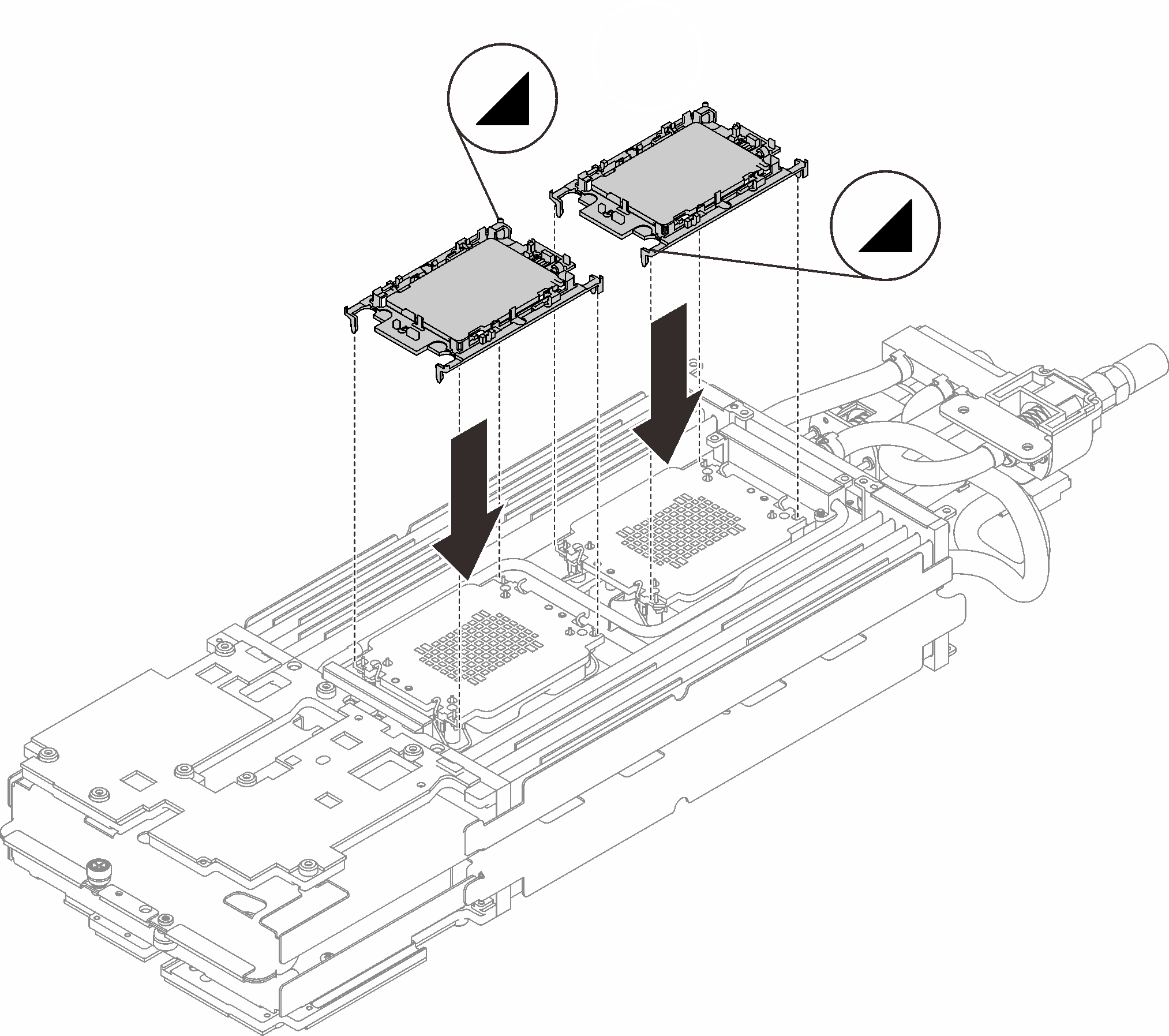
- Align the triangular marks on the processor retainers with the triangular slots on the underside of the water loop cold plate; then, attach the processors to the underside of the water loop cold plate by inserting the processor retainer posts and clips features into the openings at the four corners of the cold plate.Figure 5. Processor installation
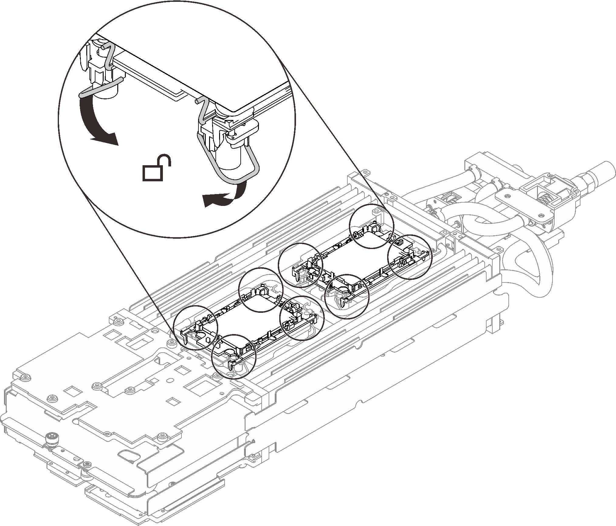
- Rotate all anti-tilt wire bails (8x anti-tilt wire bails per node) outwards to the unlocked position.Figure 6. Processor - unlocked position
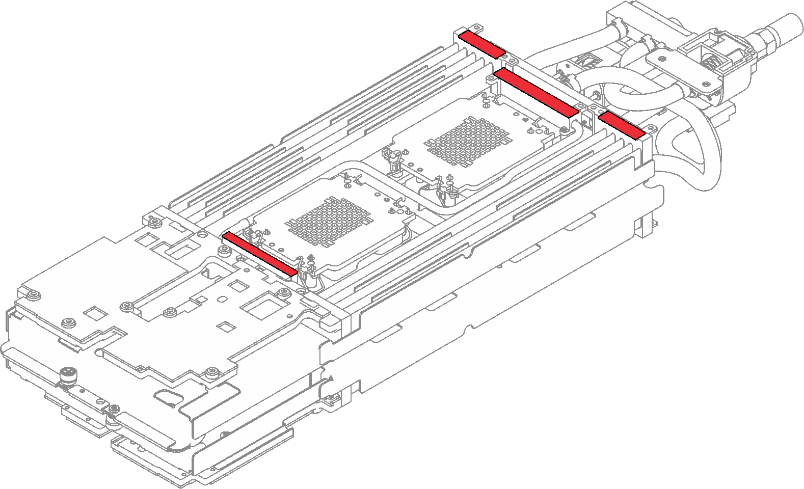
- Check the gap pads on the water loop, if any of them are damaged or missing, replace them with the new ones.Figure 7. Water loop - Gap pads
- Reinstall the water loop.
- ❶ Carefully rotate the top side of the water loop.
- ❷ Carefully insert the quick connect into the tray opening as shown.
- ❸ Carefully position the water loop on two guide pins near the rear of the node; then, gently put the water loop down and ensure it is firmly seated on the system board.
Figure 8. Water loop installation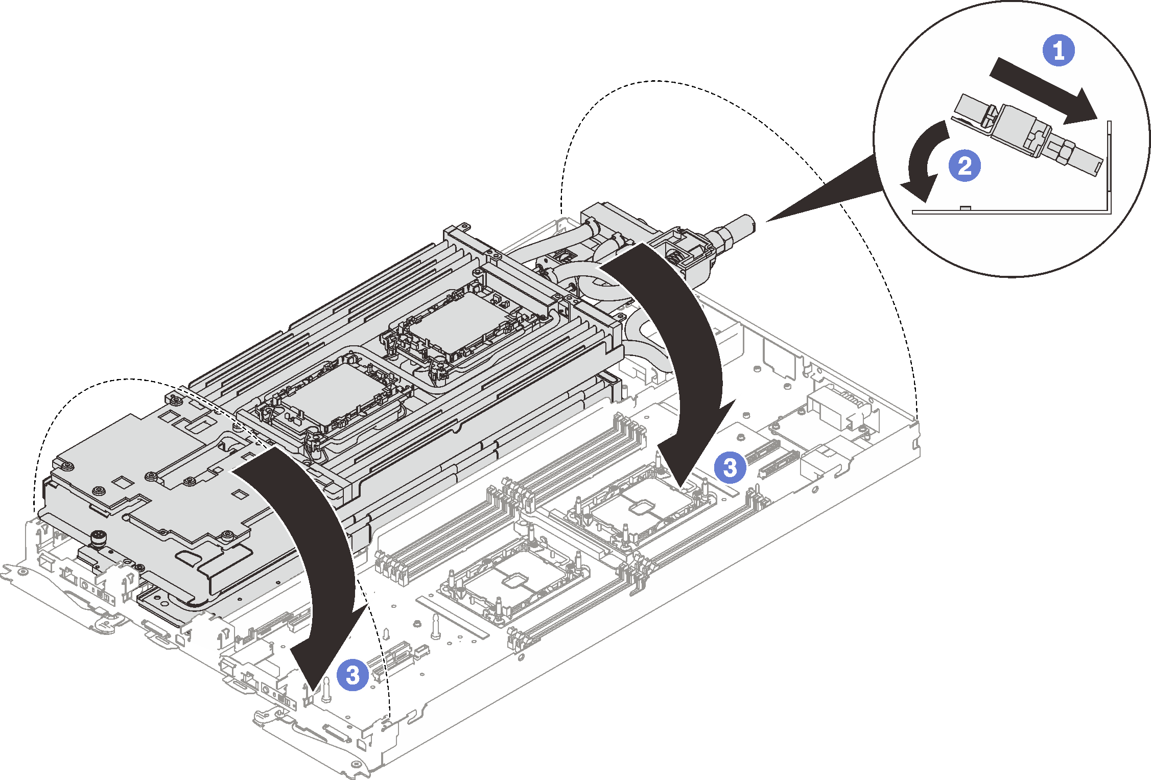
- Ensure the processors are secured properly.
- ❶ Rotate anti-tilt wire bails (8x anti-tilt wire bails per node) outwards to the locked position.
- ❷ Fully tighten all Torx T30 captive screws (8x Torx T30 captive screws per node) on cold plate with a general screwdriver until they stop, following the installation sequence shown on the cold plate label.
NoteFor reference, the torque required for the screws to be fully tightened/removed is 1.1-1.15 newton-meters, 9.8-10.2 inch-pounds.AttentionTo prevent damage to components, make sure that you follow the indicated tightening sequence.Figure 9. Processors installation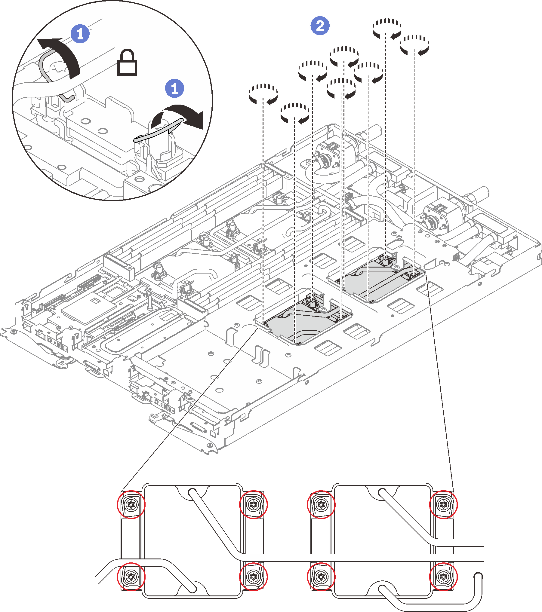
Loosen water loop carrier screws (12x Phillips #2 screws per node).
Figure 10. Loosening water loop carrier screws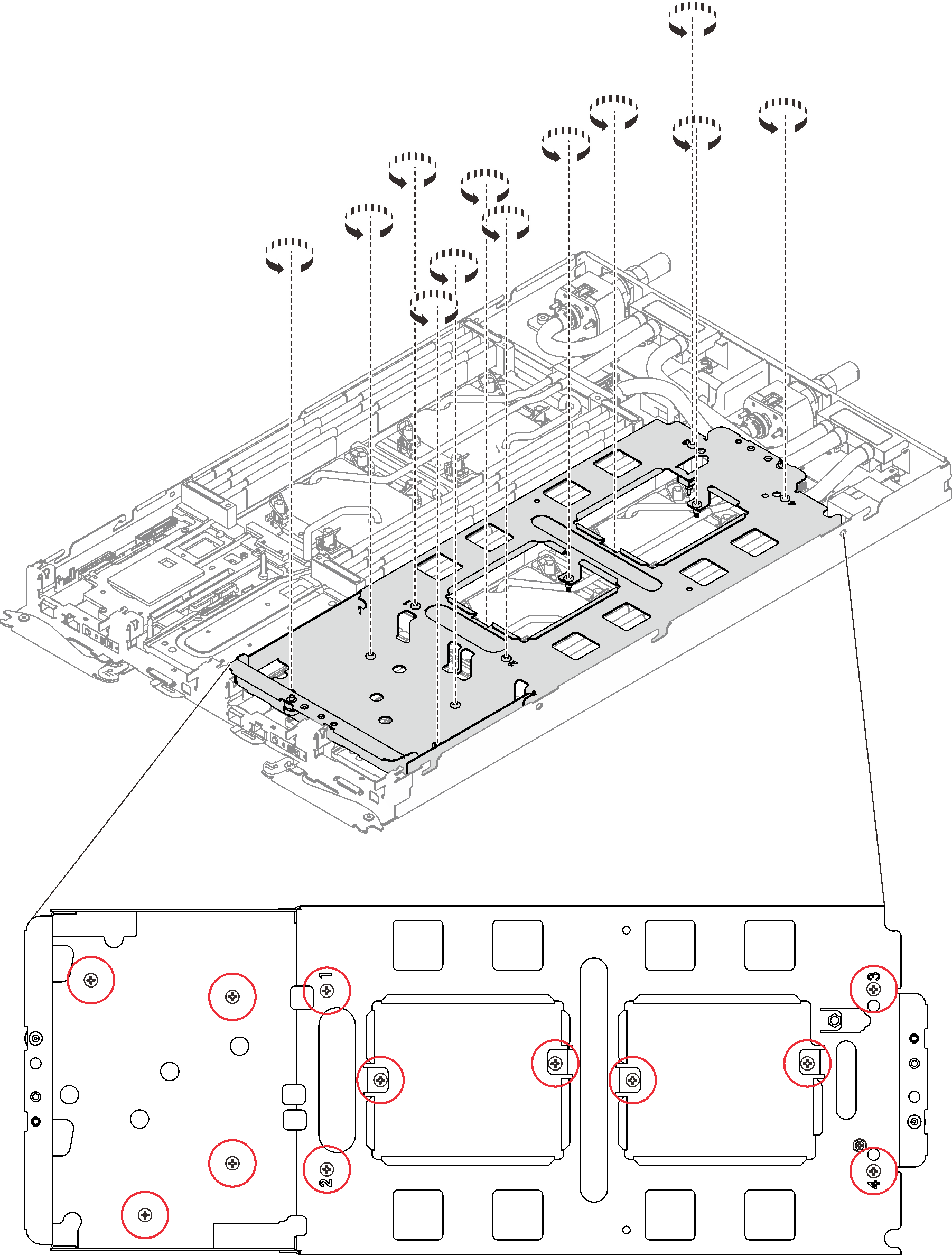
Carefully lift the water loop carrier up and away from the water loop.
Figure 11. Water loop carrier removal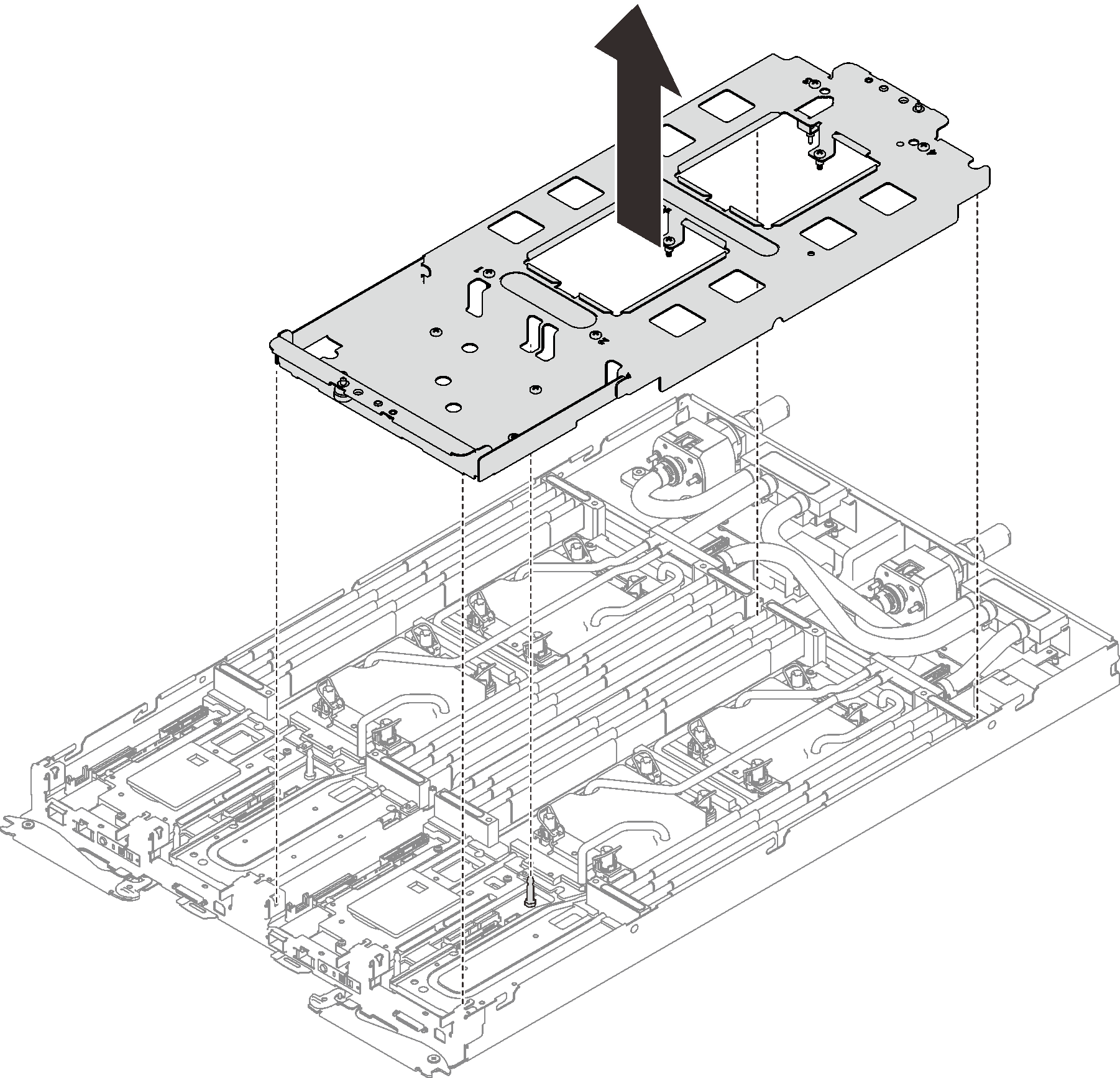
- Install the water loop screws (13x Torx T10 screws per node) with a torque screwdriver sets to the proper torque.Note
- For reference, the torque required for the screws to be fully tightened/removed is 0.5-0.6 newton-meters, 4.5-5.5 inch-pounds.
- The screw holes that are circled in blue are meant for 9.5 mm screws, while the others that are circled in red are meant for 8.0 mm ones.
Figure 12. Water loop screws installation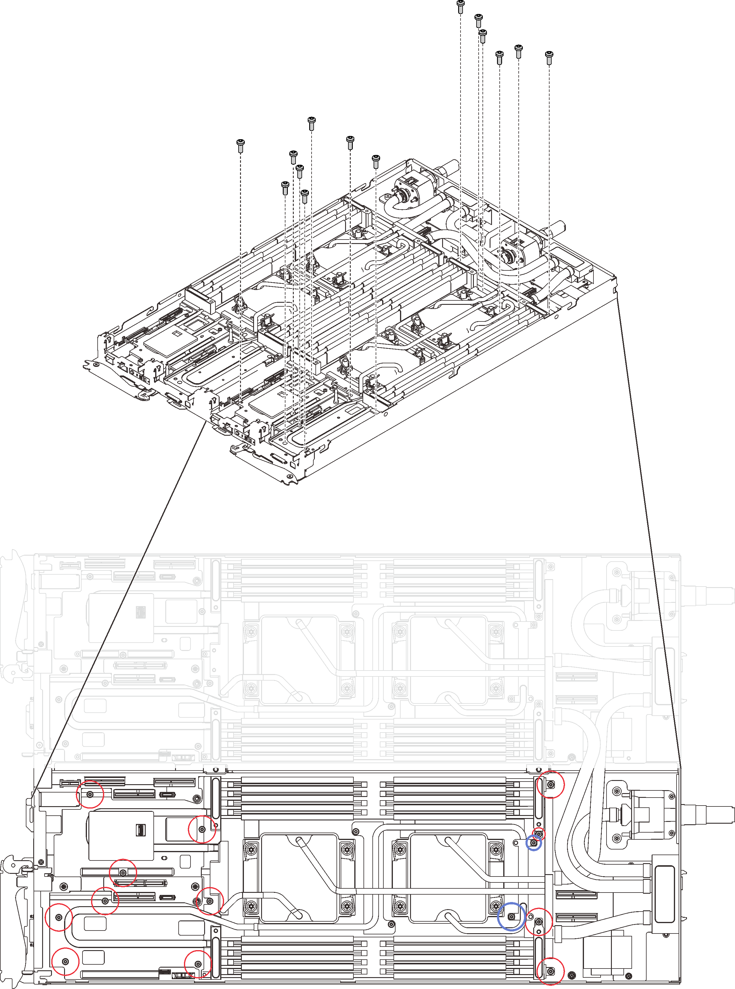
- Reinstall the following screws.
Four Torx T10 screws (per node) to secure the quick connect.
Two Phillips #1 screws (per node) on the rear of the node.
Figure 13. Screws installation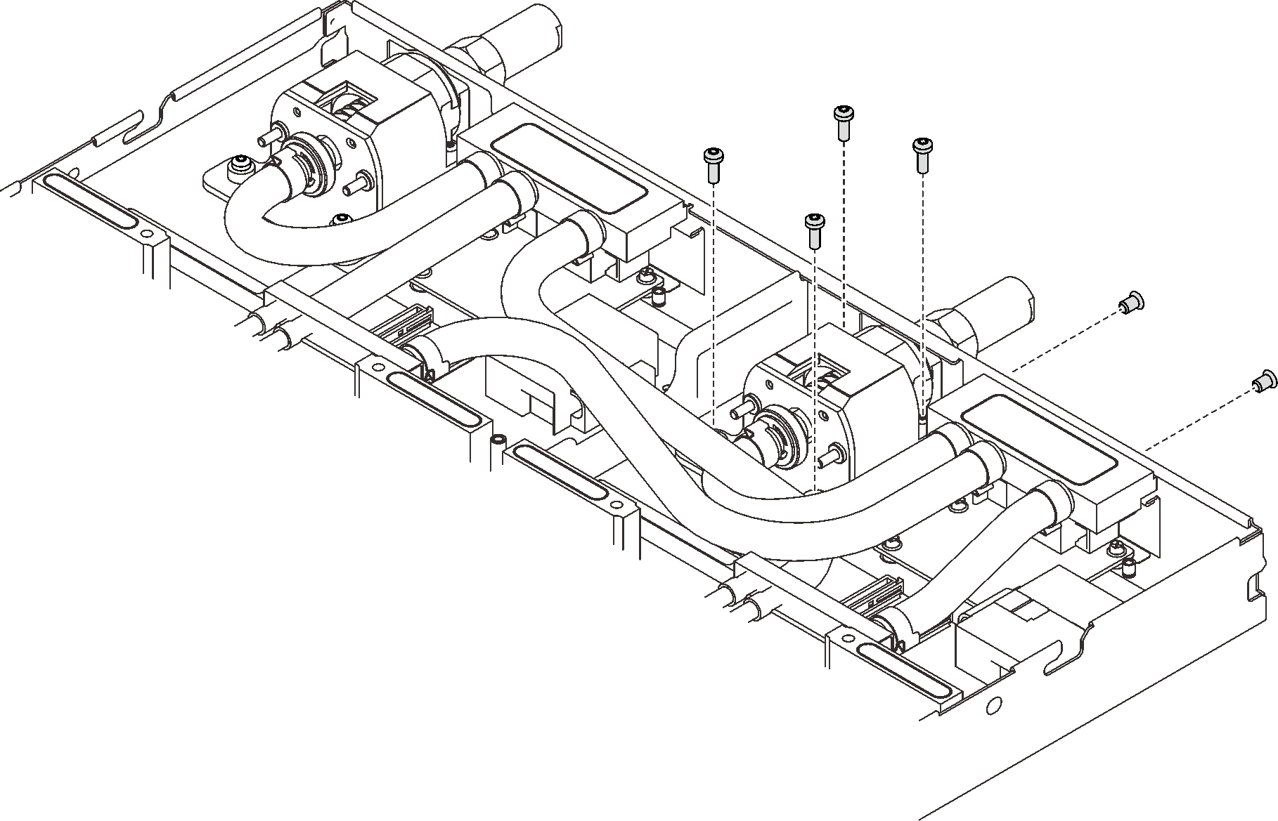
Slide the VR clamp plate into the node and install two Torx T10 screws (per node).
Figure 14. VR clamp plate installation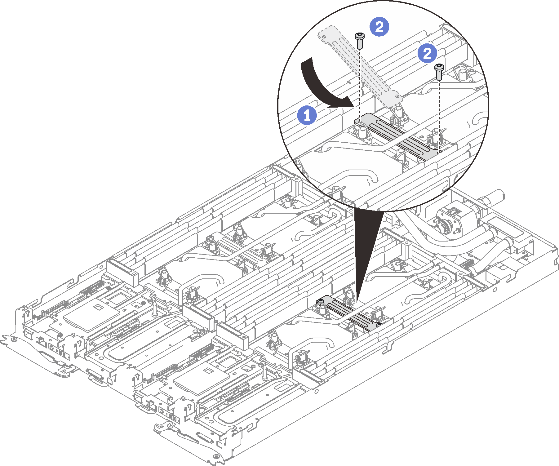
Reinstall DIMMs for both nodes (see Install a memory module).
Reinstall DIMM combs. (see Install a DIMM comb).
Reinstall M.2 backplanes (see Install the M.2 backplane).
Reinstall drive cage assemblies if applicable (see Install a drive cage assembly).
Reinstall PCIe rise assemblies if applicable (see Install a PCIe adapter).
Reinstall the front and the rear cross braces (14x Phillips #1 screws).
Figure 15. Cross brace installation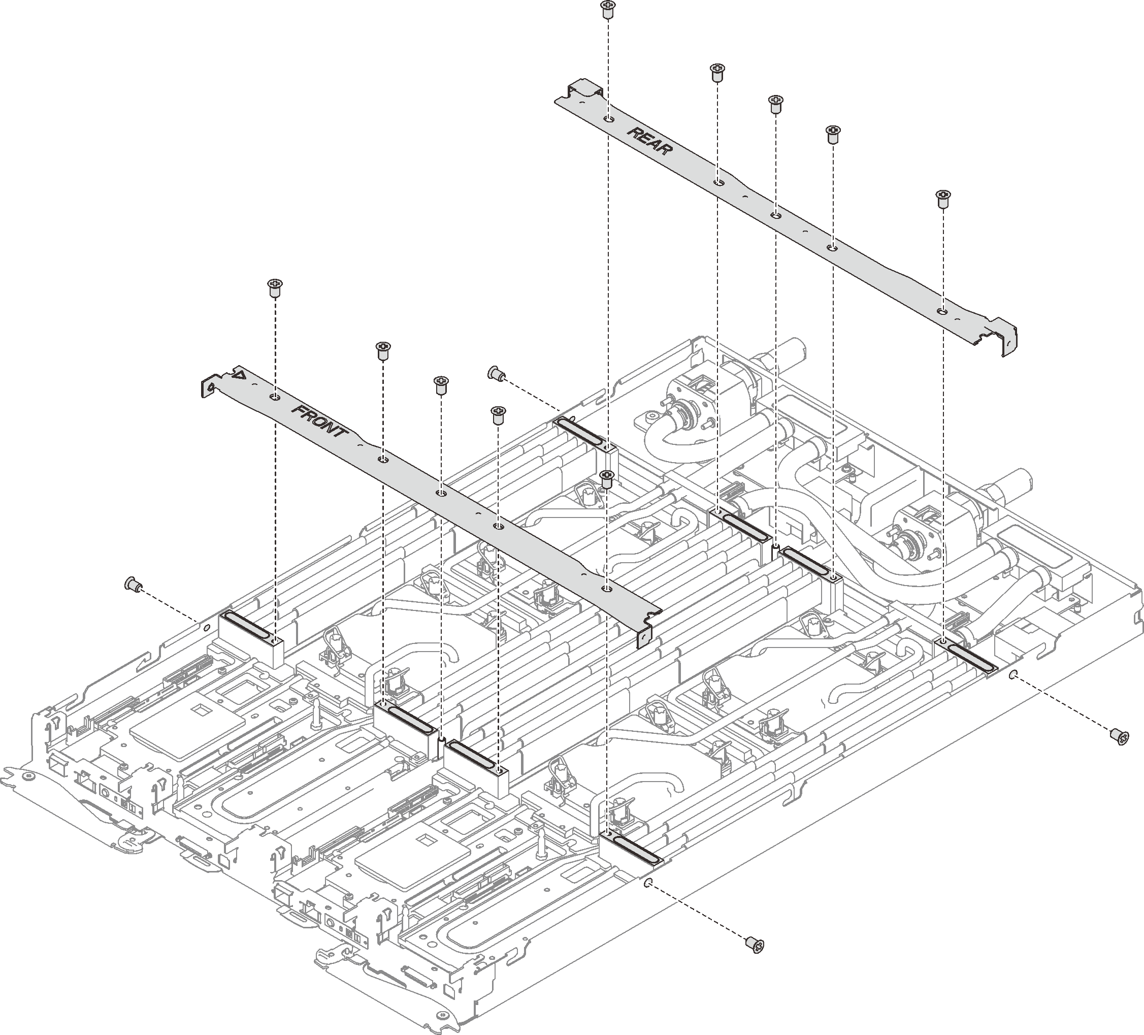
Reinstall the tray cover (see Install the tray cover).
Reinstall the tray (see Install a DWC tray in the enclosure).
NoteFor safety, use the lift tool to install the tray into the rack.- Connect all required external cables to the enclosure.NoteUse extra forces to connect QSFP cables to the enclosure if Mellanox ConnectX-6 adapters are installed.
Check the power LED on each node to make sure it changes from fast blink to slow blink to indicate all nodes are ready to be powered on.
Demo video