Remove the water loop in SD650-N V2 tray
Use this information to remove the water loop in SD650-N V2 tray.
About this task
- Read the following sections to ensure that you work safely.
- Turn off the corresponding DWC tray that you are going to perform the task on.NoteIf Shared I/O adapters are installed, power off the auxiliary node (node 1/3/5/7/9/11) first, and then power off the primary node (node 2/4/6/8/10/12).
- Disconnect all external cables from the enclosure.NoteUse extra forces to disconnect QSFP cables if they are connected to the solution.
A torque screwdriver is available for request if you do not have one at hand.
To avoid damaging the water loop, always use the water loop carrier when removing, installing or folding the water loop.
| Screwdriver Type | Screw Type |
| Torx T10 head screwdriver | Torx T10 screw |
| Phillips #1 head screwdriver or 3/16" hex head screwdriver | Phillips #1 screw |
| Phillips #2 head screwdriver | Phillips #2 screw |
Procedure
- Make preparations for this task.
- Remove the front and the rear cross braces (11x Phillips #1 screws).Figure 1. Cross brace removal
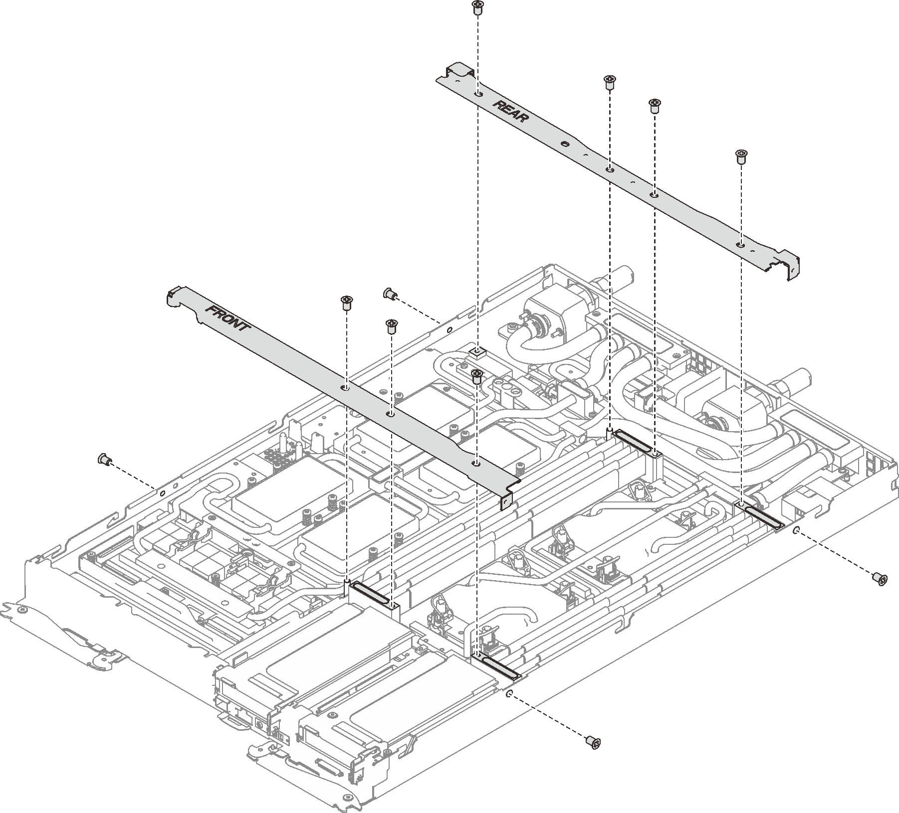
- Remove the front and the rear cross braces (11x Phillips #1 screws).Figure 2. Cross brace removal
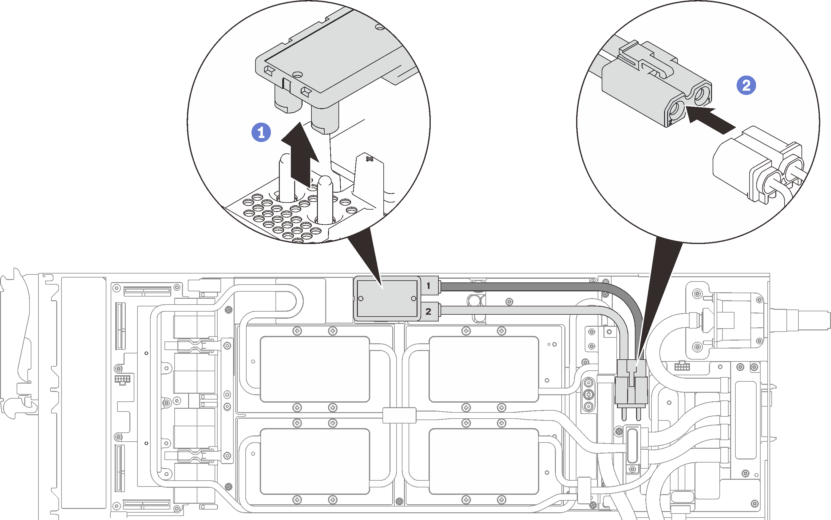
- Disconnect GPU power cable.Figure 3. GPU power cable removal
- Remove the clamp plate or the drive depending on your configuration.
Clamp plate removal: Remove the two screws to remove the clamp plate.
Figure 4. Clamp plate removal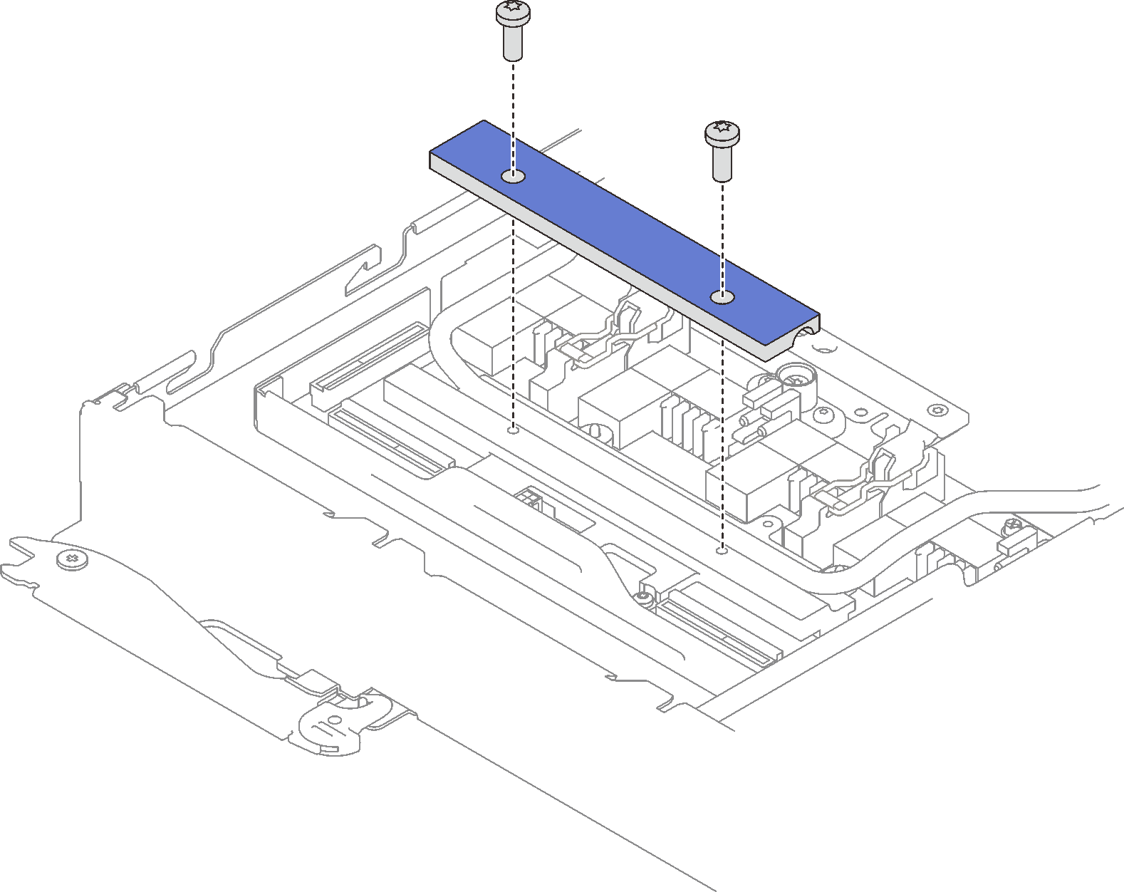
Drive removal: see Install the drive in the GPU node.
- Remove the front and the rear cross braces (11x Phillips #1 screws).
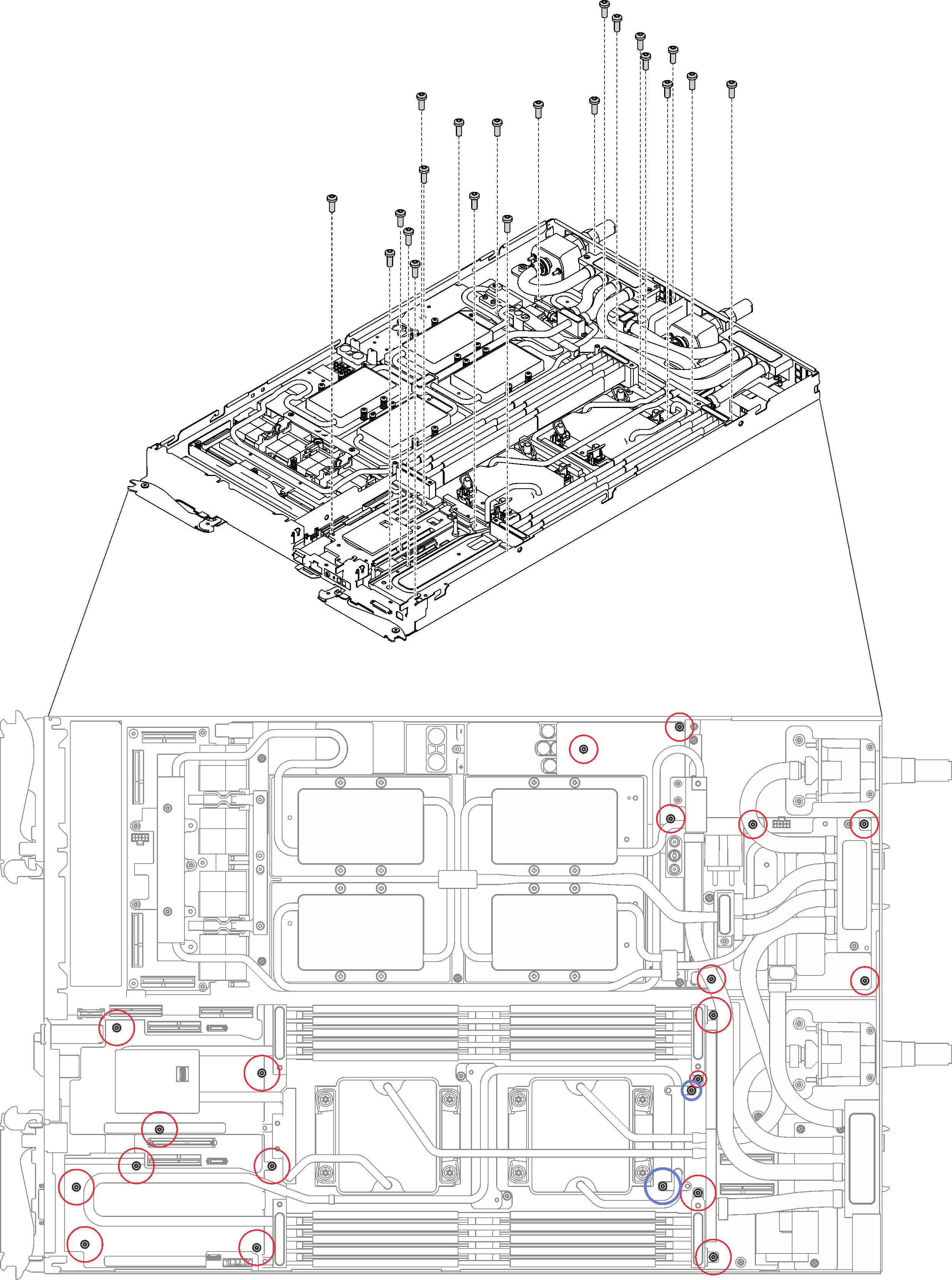
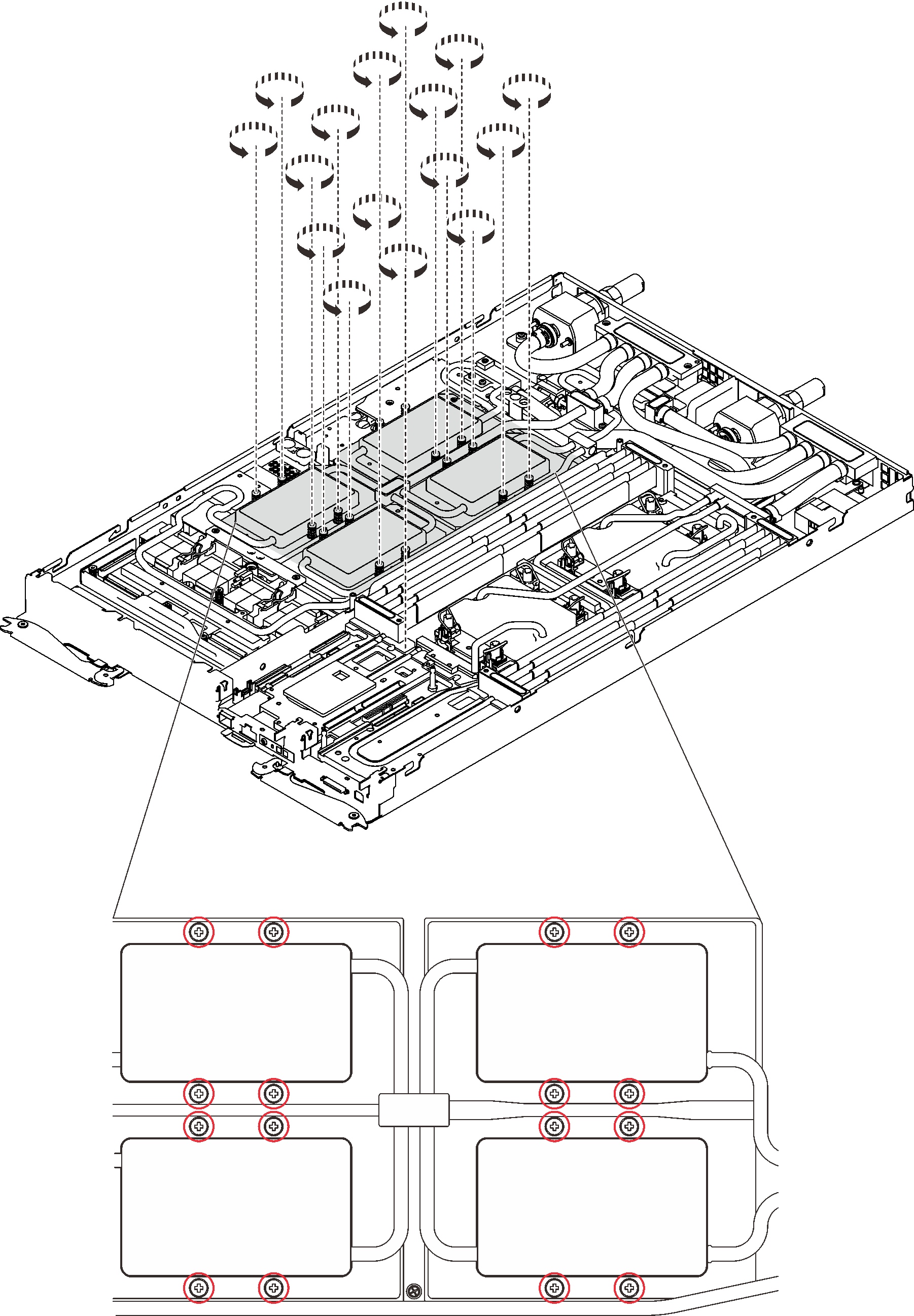
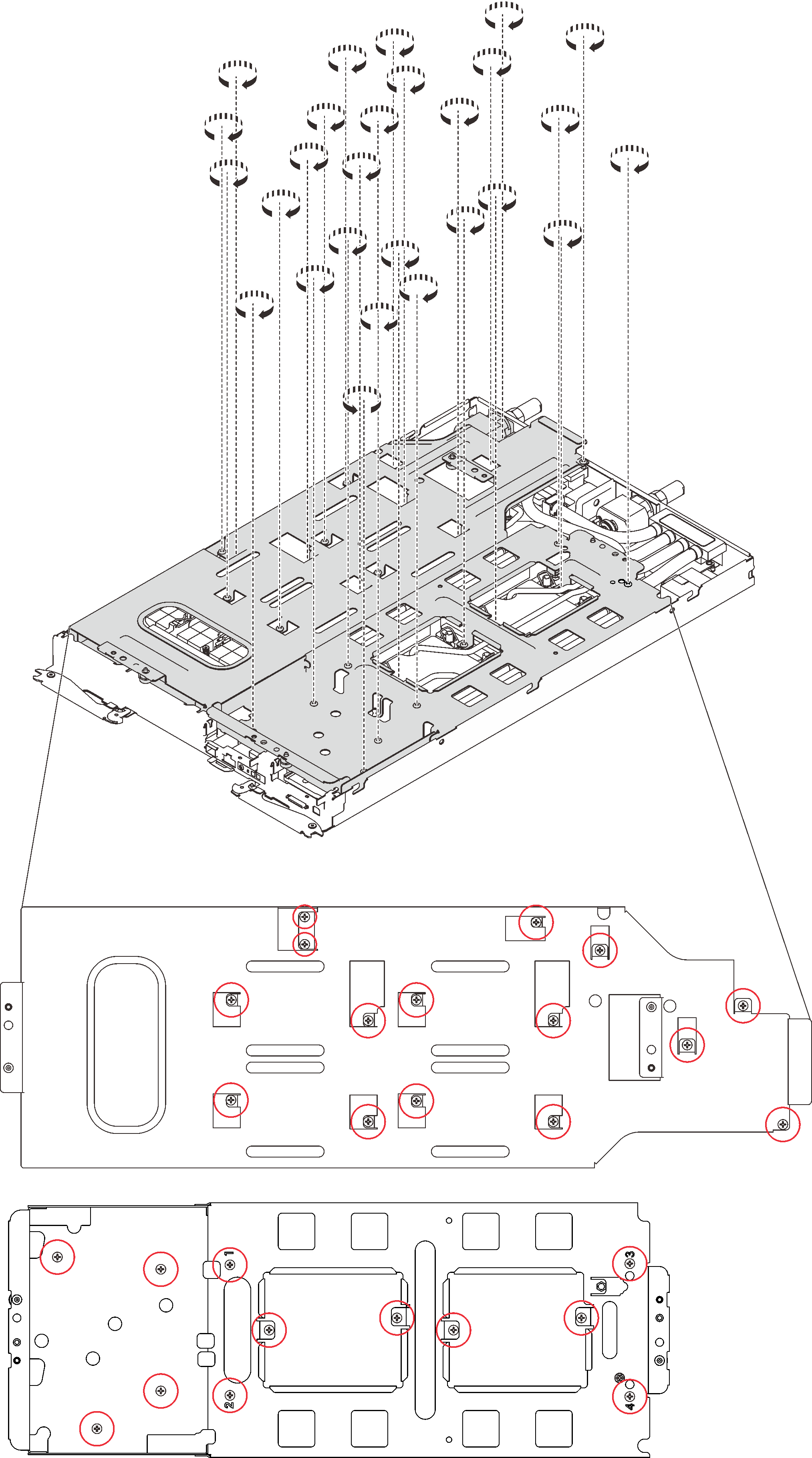
- Remove water loop screws (19x Torx T10 screws for two nodes) with a torque screwdriver sets to the proper torque.NoteFor reference, the torque required for the screws to be fully tightened/removed is 0.5-0.6 newton-meters, 4.5-5.5 inch-pounds.Figure 5. Water loop screws removal
- Remove GPU cold plate screws (16x Phillips #1 screws) with a torque screwdriver sets to the proper torque.NoteFor reference, the torque required for the screws to be fully tightened/removed is 0.34-046 newton-meters, 3-4 inch-pounds.Figure 6. GPU cold plate screws removal
- Remove the following screws to loosen the quick connect.
Eight Torx T10 screws to loosen the quick connect.
Two Phillips #1 screws on the rear of the node.
Figure 7. Screws removal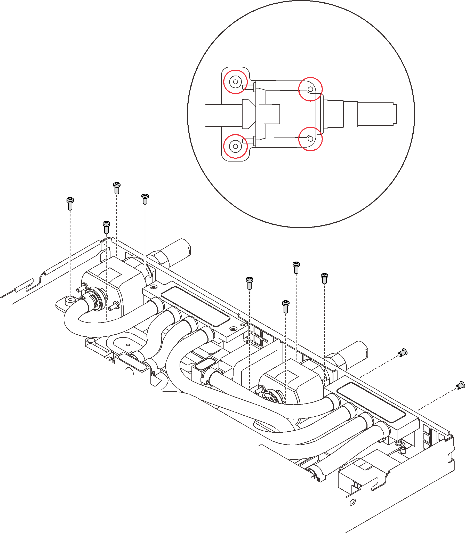
- Loosen processors properly.
- ❷ Rotate eight anti-tilt wire bails inwards to the unlocked position.Figure 8. Loosening Torx T30 captive screws
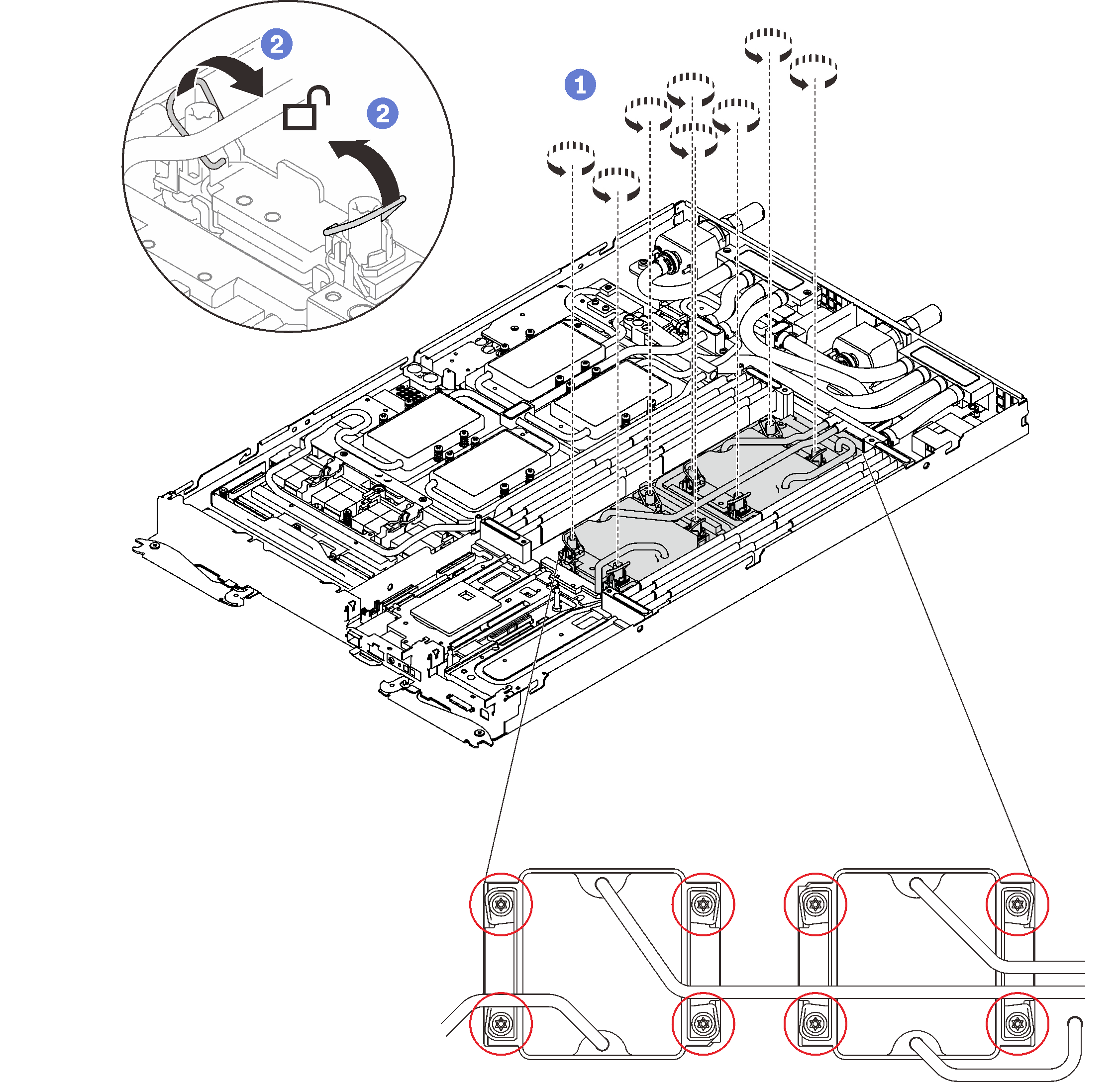
- ❷ Rotate eight anti-tilt wire bails inwards to the unlocked position.
- Orient two water loop carriers with the guide pins; then, gently put two water loop carriers down and ensure they are seated firmly on the water loop.Figure 9. Water loop carrier installation
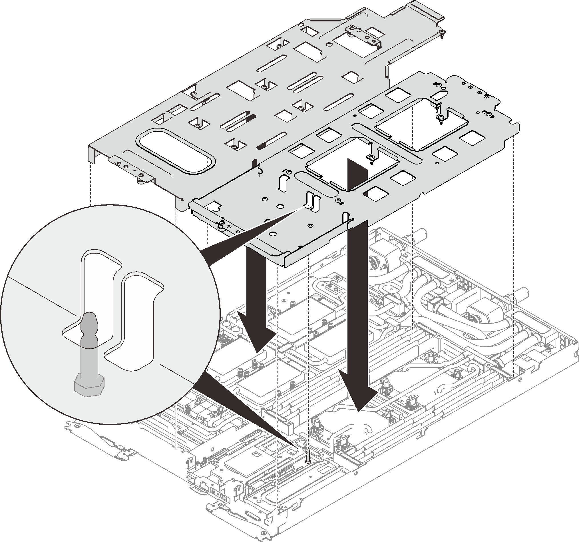
- Tighten water loop carrier screws (27x Phillips #2 screws for two nodes).Figure 10. Water loop carrier screws installation
- Fold the water loop.
❶ Carefully unhook the quick connect and slide it out of the opening in the rear of the tray; then, lift the water loop up off the system board.
❷ Carefully rotate the water loop so one half is sitting on top of the other half.
Figure 11. Folding the water loop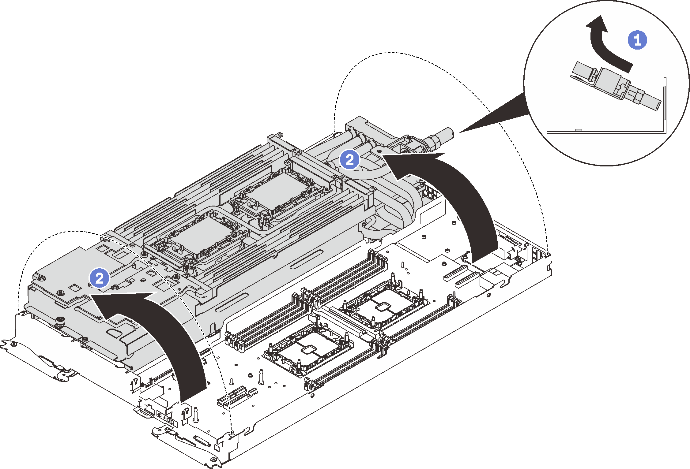
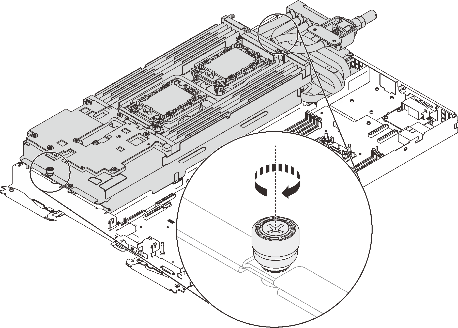
- Fasten two captive thumbscrews to secure water loop carriers to each other.Figure 12. Tightening captive thumbscrews
- Remove the water loop.
- Carefully lift the water loop up off the system board.
- Unhook the quick connect from the four alignment posts and slide the quick connect out of the opening in the rear of the tray.
- Lift the water loop out of the node.
Figure 13. Water loop removal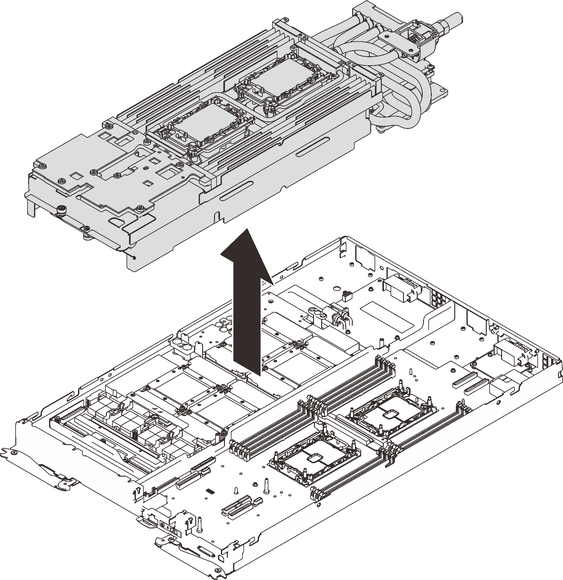
If you are instructed to return the component or optional device, follow all packaging instructions, and use any packaging materials for shipping that are supplied to you.
Demo video