Install the CMOS battery (CR2032)
Use this information to install the CMOS battery.
About this task
- S004
 CAUTION
When replacing the lithium battery, use only Lenovo specified part number or an equivalent type of battery recommended by the manufacturer. If your system has a module containing a lithium battery, replace it only with the same module type made by the same manufacturer. The battery contains lithium and can explode if not properly used, handled, or disposed of.
Do not:- Throw or immerse into water
- Heat to more than 100°C (212°F)
- Repair or disassemble
Dispose of the battery as required by local ordinances or regulations.
- S005CAUTIONThe battery is a lithium ion battery. To avoid possible explosion, do not burn the battery. Exchange it only with the approved part. Recycle or discard the battery as instructed by local regulations.
Read Installation Guidelines and Safety inspection checklist to ensure that you work safely.
The following notes describe information that you must consider when replacing the system battery in the node.
- When replacing the system battery, you must replace it with a lithium battery of the same type from the same manufacturer.
- After you replace the system-board battery, you must reconfigure the node and reset the system date and time.
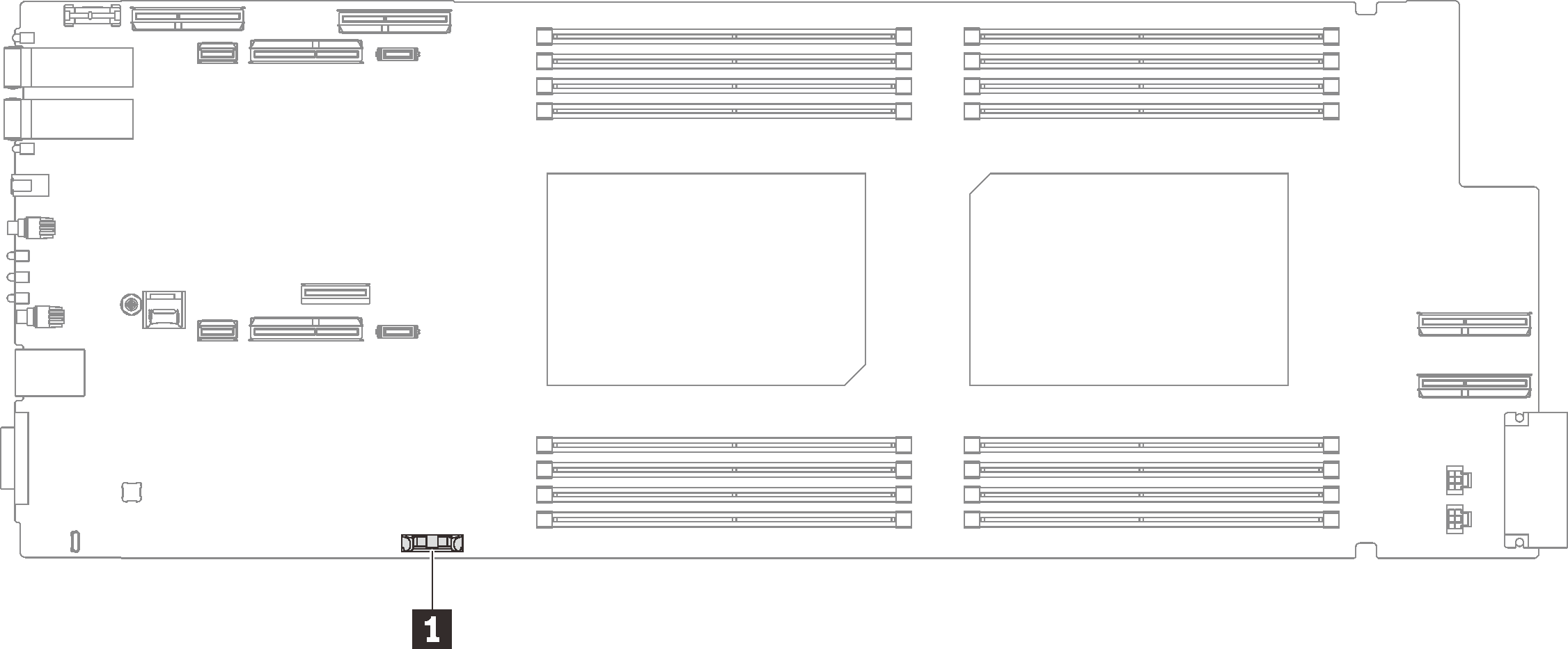
| 1 CMOS battery |
Procedure
- Follow any special handling and installation instructions that come with the CMOS battery.
- Insert the new CMOS battery:
- As you slide the CMOS battery into place, press the top of the CMOS battery into the socket. Make sure that the battery clip holds the battery securely.Figure 2. CMOS battery installation
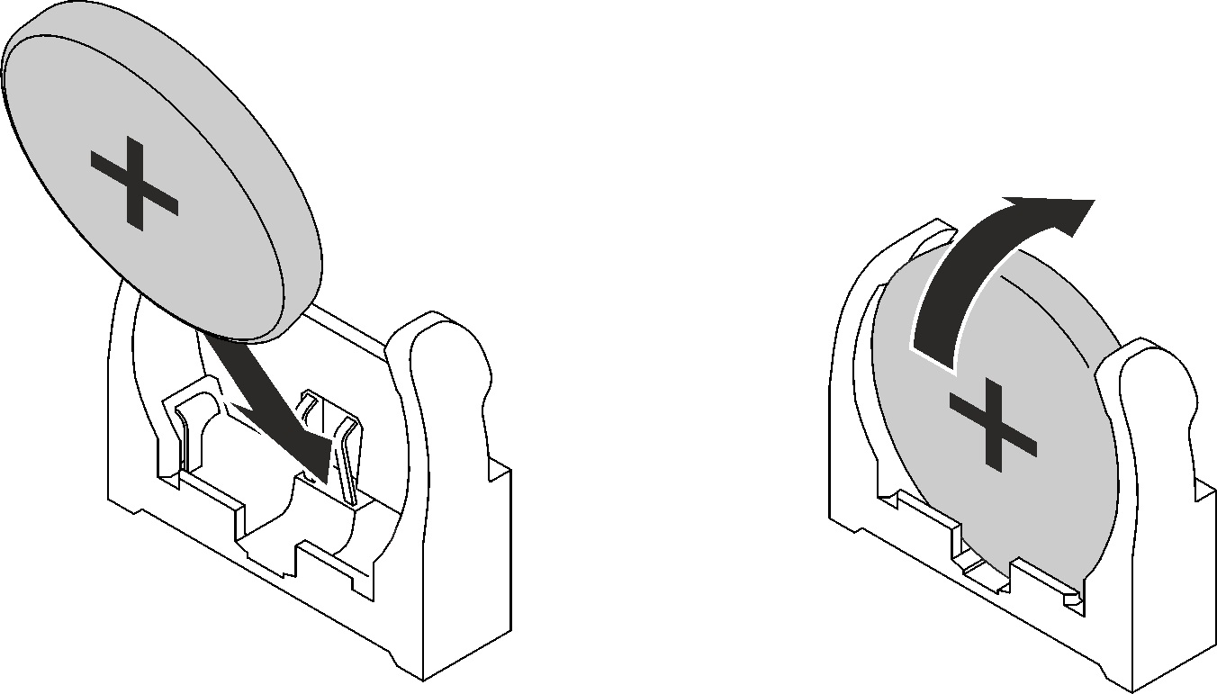
- As you slide the CMOS battery into place, press the top of the CMOS battery into the socket. Make sure that the battery clip holds the battery securely.
Install the PCIe riser assembly. See Install a PCIe riser assembly (ConnectX-6) , PCIe riser assembly replacement (ConnectX-7 NDR 200), or Install a PCIe riser assembly (ConnectX-7 NDR 400).
Install the tray cover. See Install the tray cover.
Install the tray into the enclosure. See Install a DWC tray in the enclosure.
- Connect all required external cables to the solution.NoteUse extra force to connect QSFP cables to the solution.
Check the power LED on each node to make sure it changes from fast blink to slow blink to indicate all nodes are ready to be powered on.
Demo video