Install the TCM/TPM adapter (for Chinese Mainland only)
Use this information to install the TCM/TPM adapter.
Before installing the TCM/TPM adapter, touch the static-protective package that contains the new TCM/TPM adapter to any unpainted surface on the outside of the server. Then, take the new TCM/TPM adapter out of the package and place it on a static-protective surface.
Read the Installation Guidelines to ensure that you work safely.
- TCM/TPM adapter is the unique component for the nodes that are sold in Chinese Mainland.
- When the TCM/TPM adapter is removed, all TCM/TPM functions will be disabled.
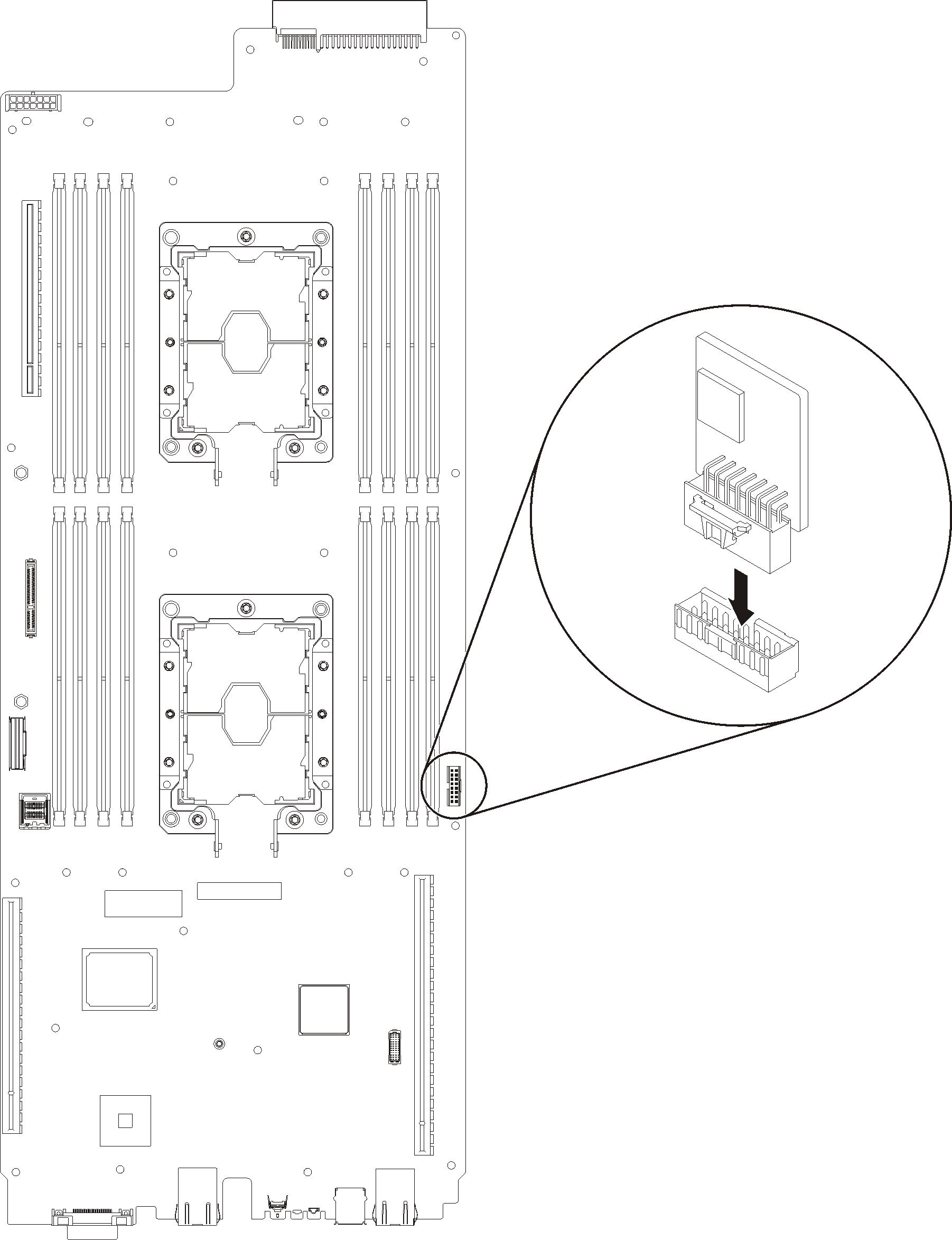
Complete the following steps to install the TCM/TPM adapter.
After you install the TCM/TPM, complete the following steps:
Reinstall the system board (see Install a system board).
Reinstall the blank bezel filler.
Figure 2. Blank bezel filler installation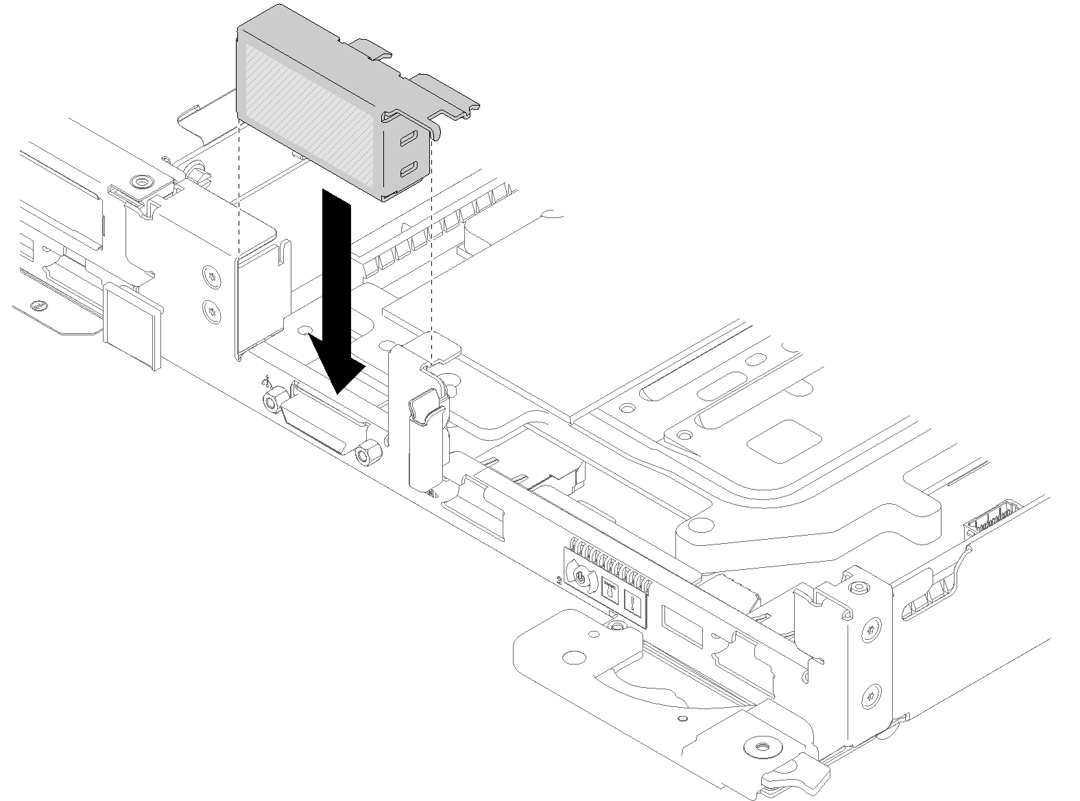
Reinstall the power distribution board (see Install the power distribution board).
Reinstall the water loop.
Carefully rotate the top side of the water loop.
Carefully insert the quick connect into the tray opening as shown.
Lower and orient the water loop carrier over the M.2 backplane planes; then, ensure the processor socket guide pins fit correctly through holes in the water loop cold plates.
Gently put the other side of the water loop down and ensure it is seated firmly on the system board.
Figure 3. Water loop installation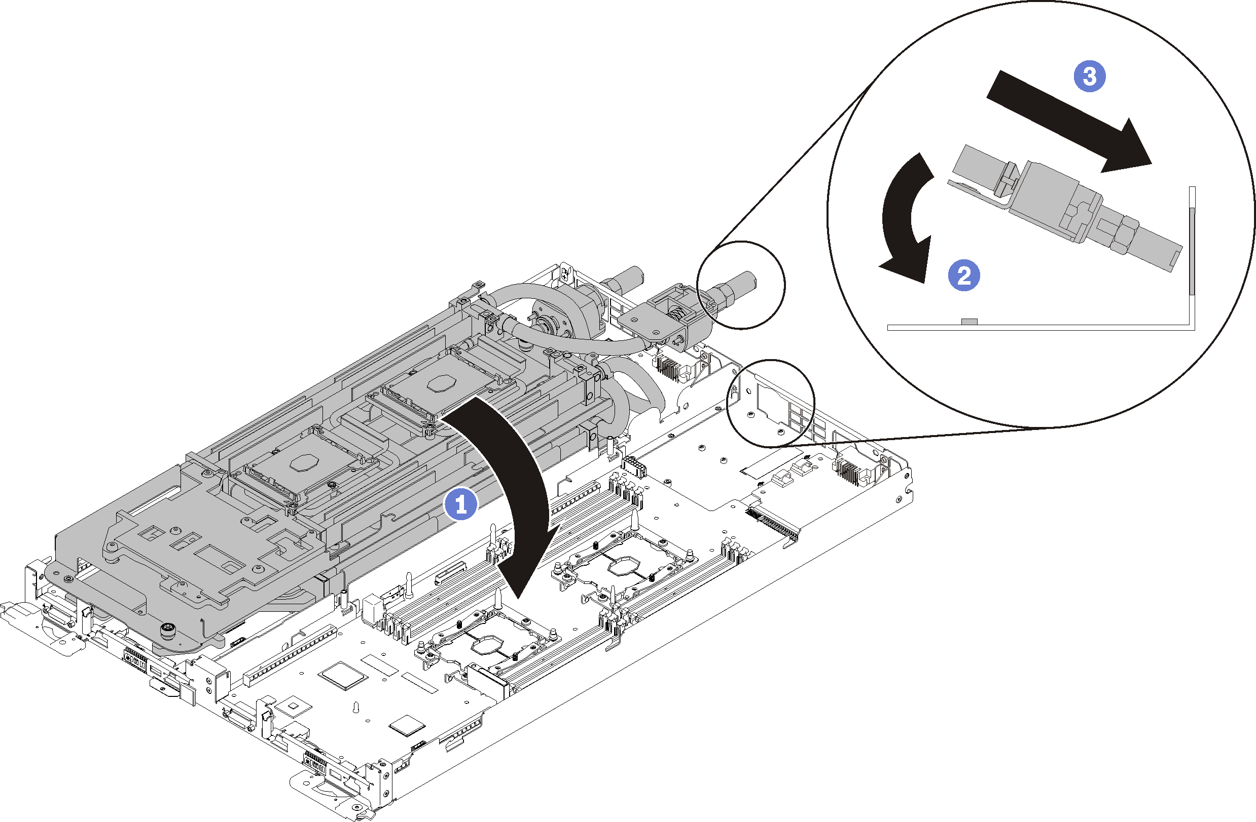
Hook two quick connects.
Secure the water loop and the quick connect to the tray by carefully inserting 15 silver Torx T10 screws.
Figure 4. Silver T10 screw installation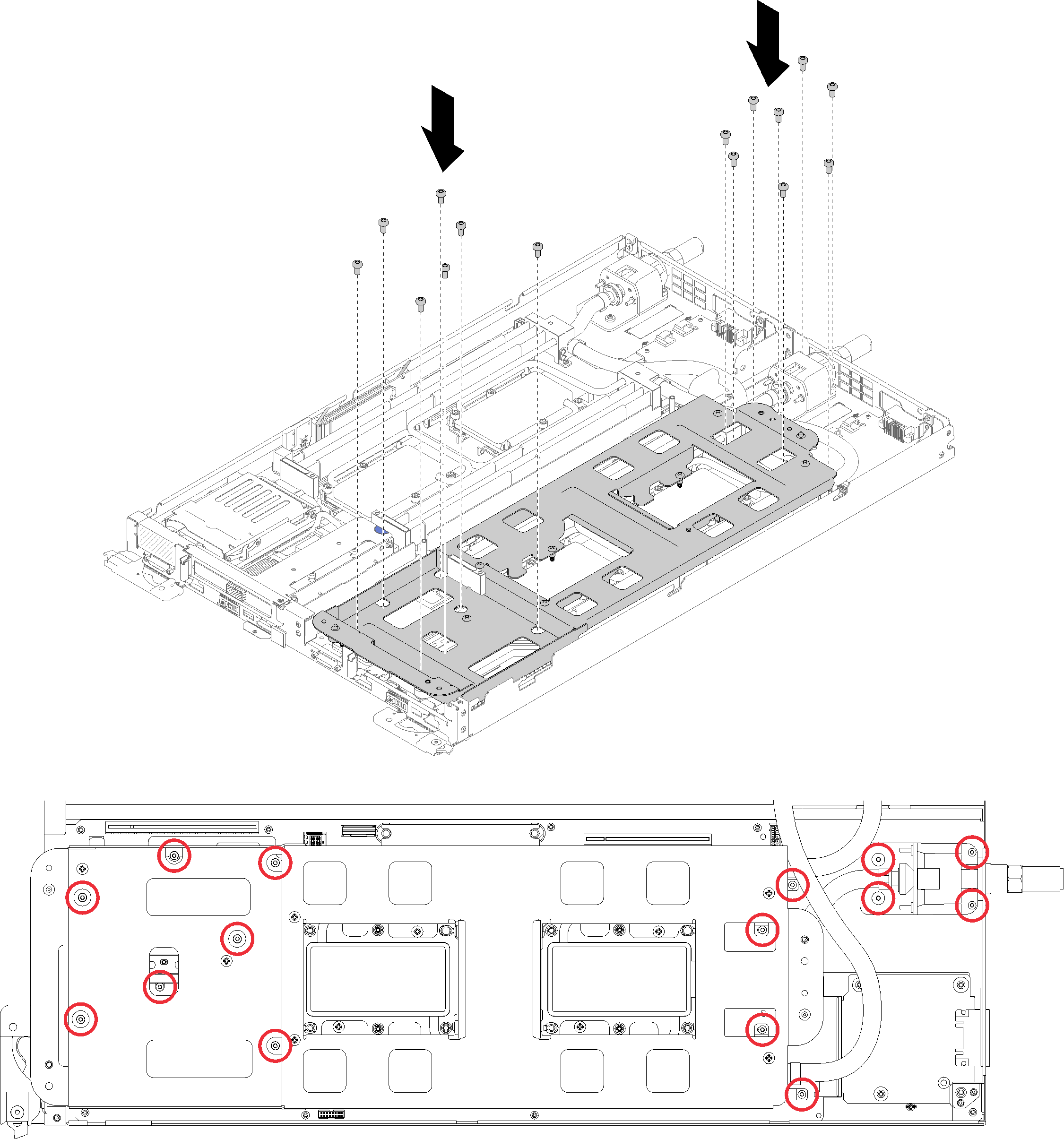
Loosen water loop carrier screws (10x P2 screws per node).
Figure 5. Loosening captive P2 screws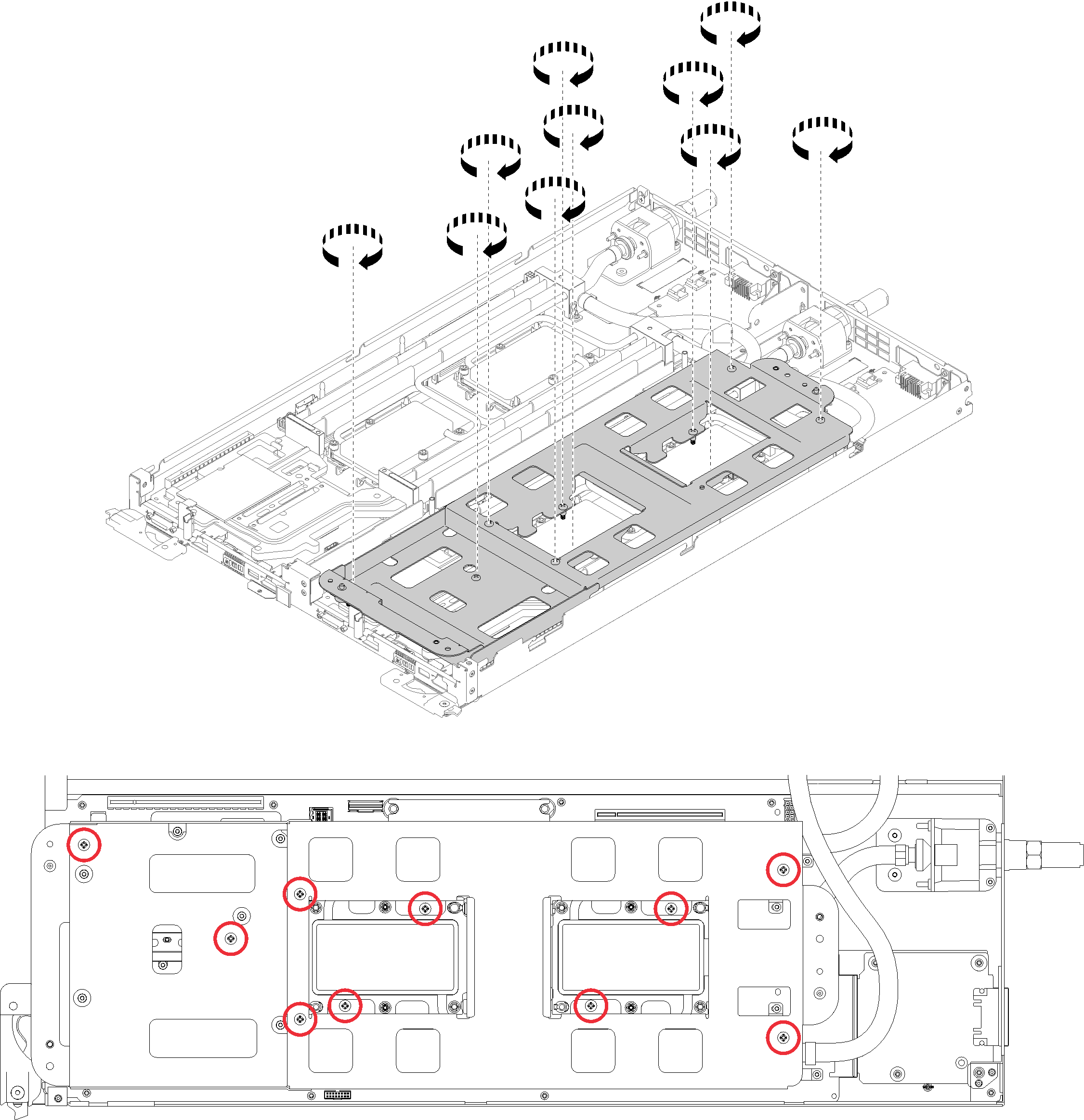
Fully tighten all Torx T30 captive fasteners (8x Torx T30 captive fasteners per node) on cold plates in the installation sequence shown on the cold plate label.
AttentionTo prevent damage to components, make sure that you follow the indicated tightening sequence.Figure 6. Tightening screws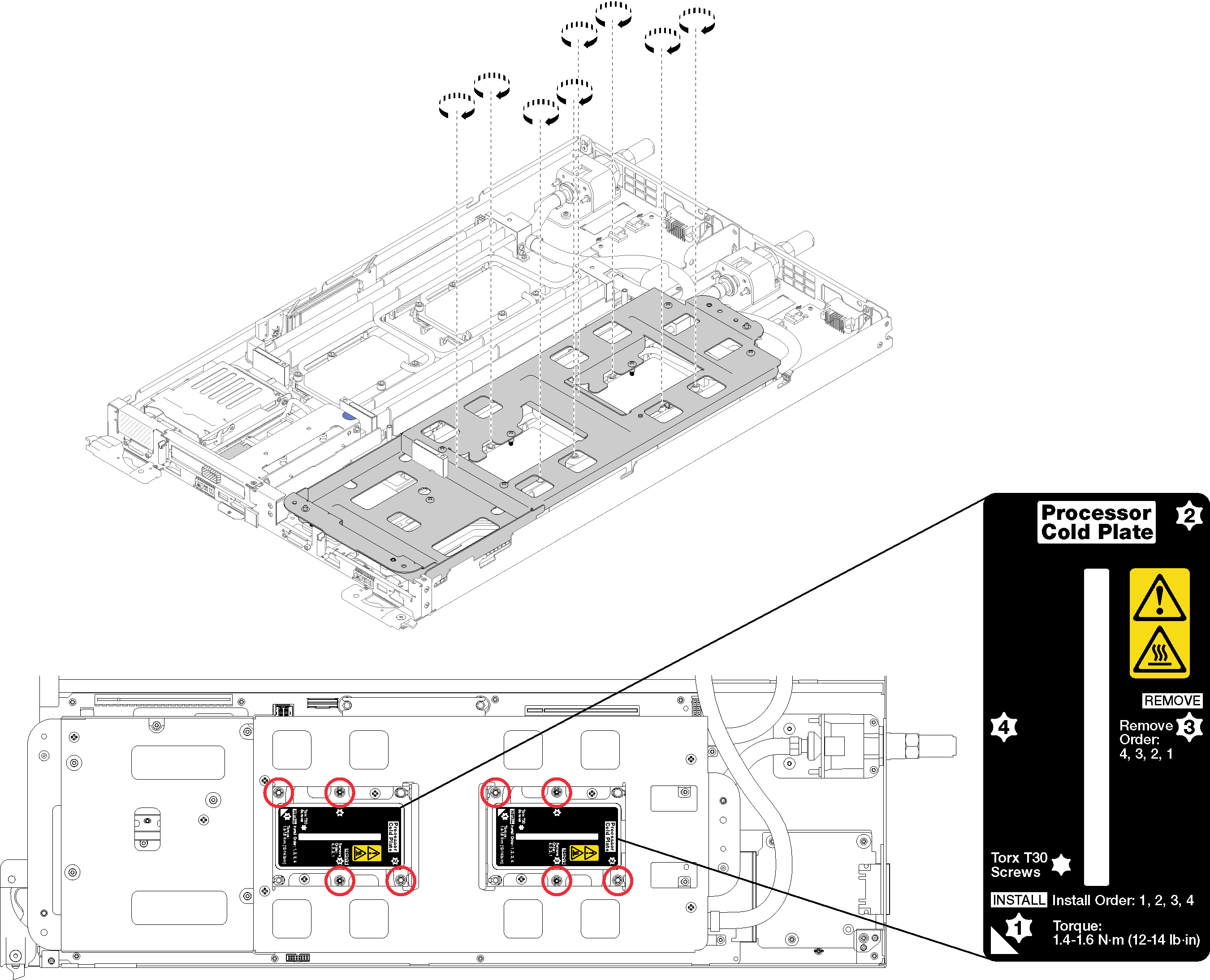
Carefully lift the water loop carrier up and away from the water loop.
Figure 7. Water loop carrier removal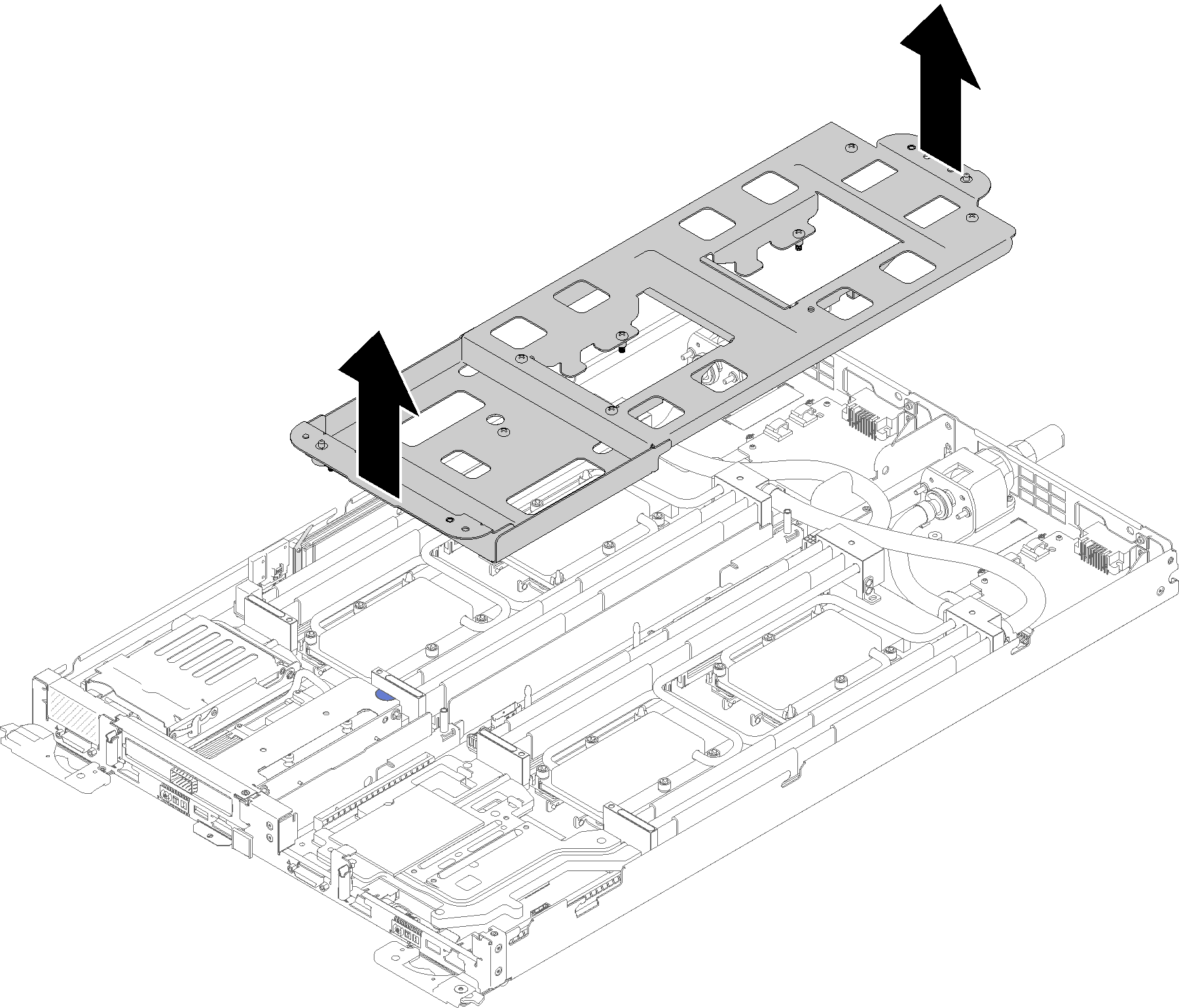
Reinstall all four DIMM covers and DIMMs for both nodes (see Install a DIMM).
Reinstall M.2 backplanes for both nodes (see Install the M.2 backplane).
Reinstall drive cage assemblies if applicable (see Install a drive cage assembly).
Reinstall PCIe rise assemblies if applicable (see Install an adapter or Install an Internal Faceplate Transition (IFT) adapterdepending on your configuration).
Reinstall both air baffles.
Figure 8. Air baffle installation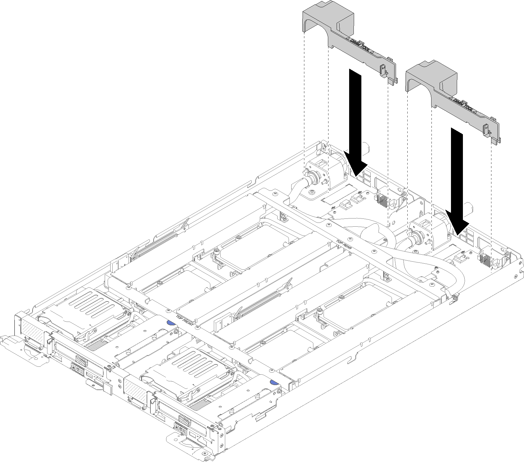
Reinstall the front and the rear cross braces (10x P2 screws).
Figure 9. Cross brace installation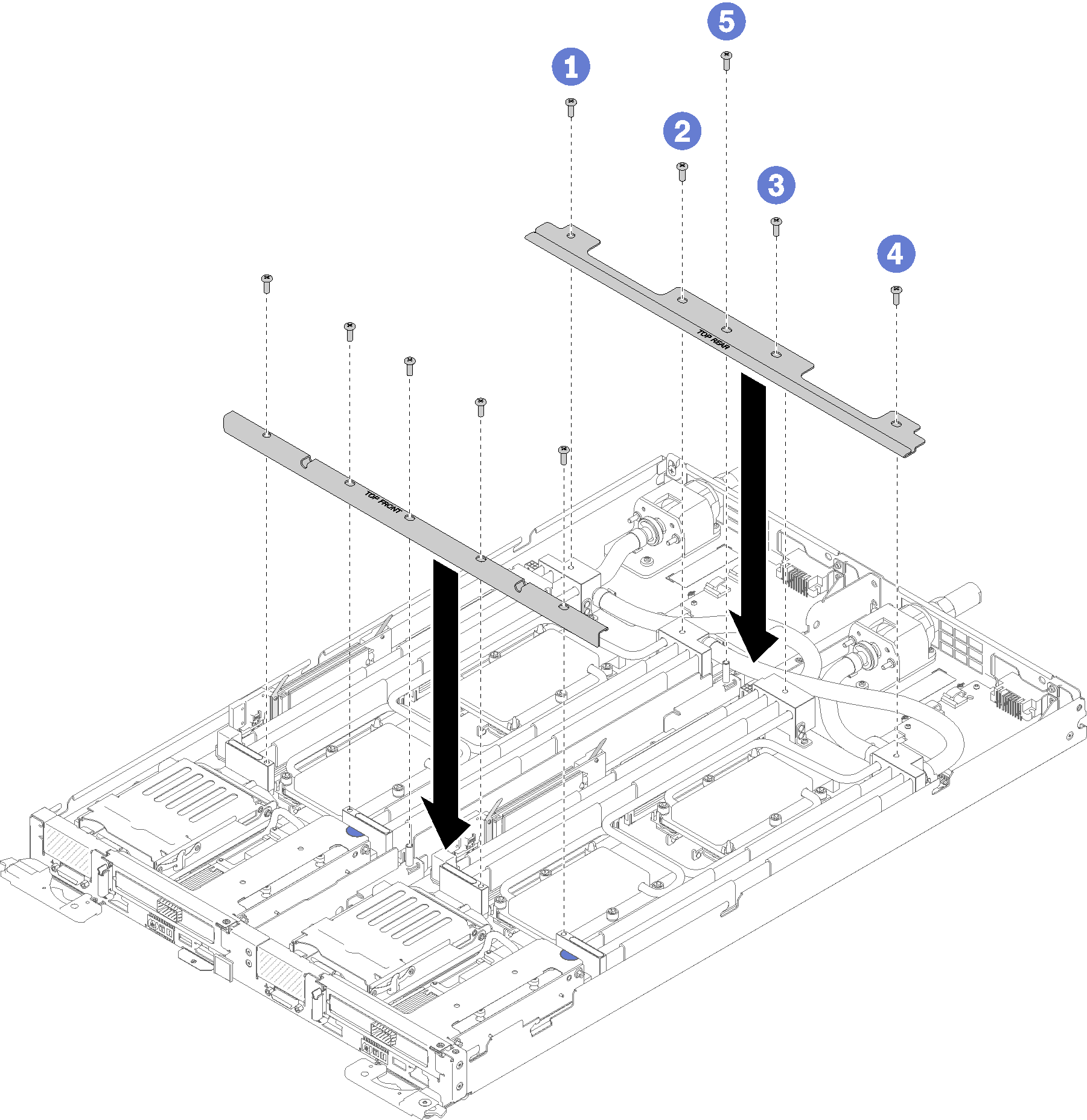
Reinstall the tray cover (see Install the tray cover).
Reinstall the tray (see Install a DWC tray in the enclosure).
Check the power LED on each node to make sure it changes from fast blink to slow blink to indicate both nodes are ready to be powered on.
Demo video