Remove the processor heat sink
Follow instructions in this section to remove the processor heat sink. This procedure must be executed by a trained technician.
About this task

Read Installation Guidelines and Safety inspection checklist to ensure that you work safely.
Power off the server and peripheral devices and disconnect the power cords and all external cables. See Power off the server.
Prevent exposure to static electricity, which might lead to system halt and loss of data, by keeping static-sensitive components in their static-protective packages until installation, and handling these devices with an electrostatic-discharge wrist strap or other grounding system.
Do not allow the thermal grease on the processor or heat sink to come in contact with anything. Contact with any surface can compromise the thermal grease, rendering it ineffective. Thermal grease can damage components, such as the electrical connectors in the processor socket.
If the node is installed in an enclosure or mounted, remove the node from the enclosure or mount. See Configuration guide.
Procedure
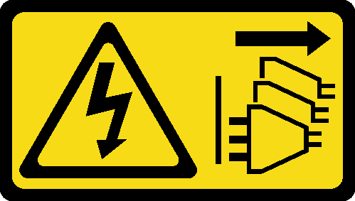
- Remove the screws from the top cover.
 Slide the pull-out information tabs outward from the node.
 Remove the four Phillips #1 screws located on the short side of the top cover.Note
Make sure to slide the pull-out information tabs back once the screw underneath is fully removed.
 Remove the four Phillips #2 screws located on the long side of the top cover; then, reverse the node and place the bottom side of the node facing up.Note
The screws to be removed might be covered by fan cables. Carefully pull the fan cable out a little bit to remove the screw underneath, and put the cable back after removing the screw.
Figure 1. Removing screws from the top cover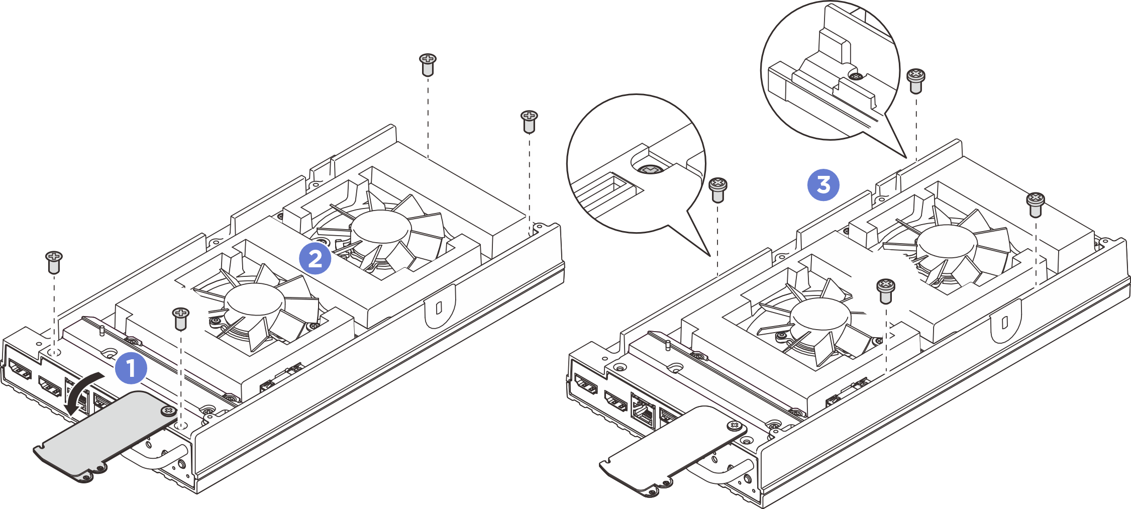
- Remove the bottom cover.
- Remove the two Phillips #1 screws located on the short side of the bottom cover.
- Remove the six Phillips #2 screws from the long side of the bottom cover.
- Hold the blue touch points on the rear side of the node and the I/O bracket handle on the front side of the node; then pull the front and rear I/O brackets from the node.
-
 Lift up the bottom cover from the node, and place it on a flat clean surface.
AttentionTo make sure that there is adequate system cooling, install both top cover and bottom cover before powering on the server. Operating the server with the covers removed might damage server components.Figure 2. Removing the bottom cover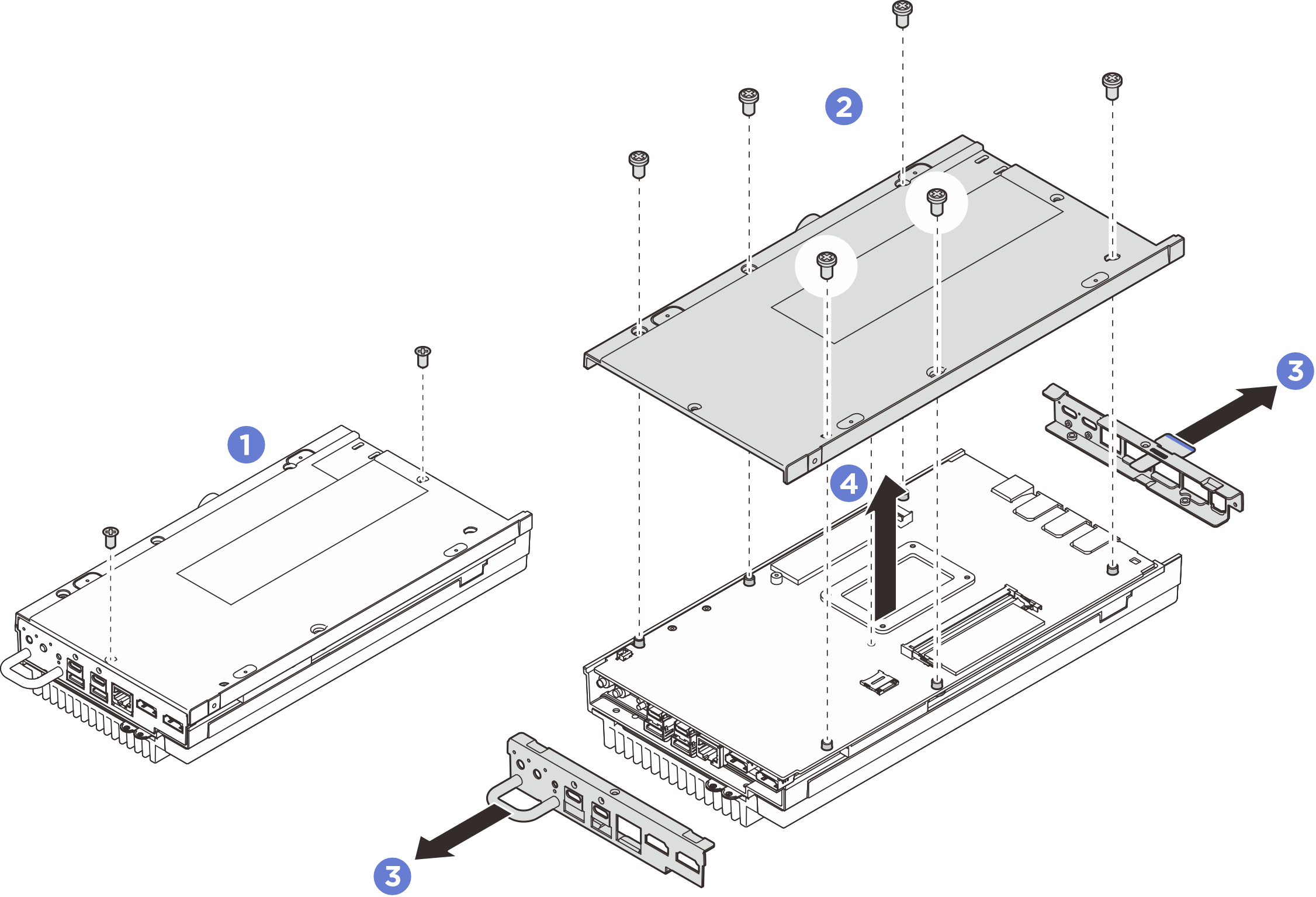
- Separate the system board from the top cover.
- Carefully separate the front I/O side of system board from the top cover.
- Gently lift up the rear I/O side of the system board until the system board is fully separated from the top cover.
- Lift up the system board to remove it from the top cover. Hold both sides of the system board and turn it over to let the top side of the system board up; then place it on a static-protective surface.Figure 3. Removing the system board
- Remove the processor heat sink.
- Follow the screw sequence to shown in the illustration to partially loosen the screws that secure heat sink; then, follow the same sequence to fully loosen the screws.
- Lift the heat sink evenly to remove it from the server.
Figure 4. Removing the processor heat sink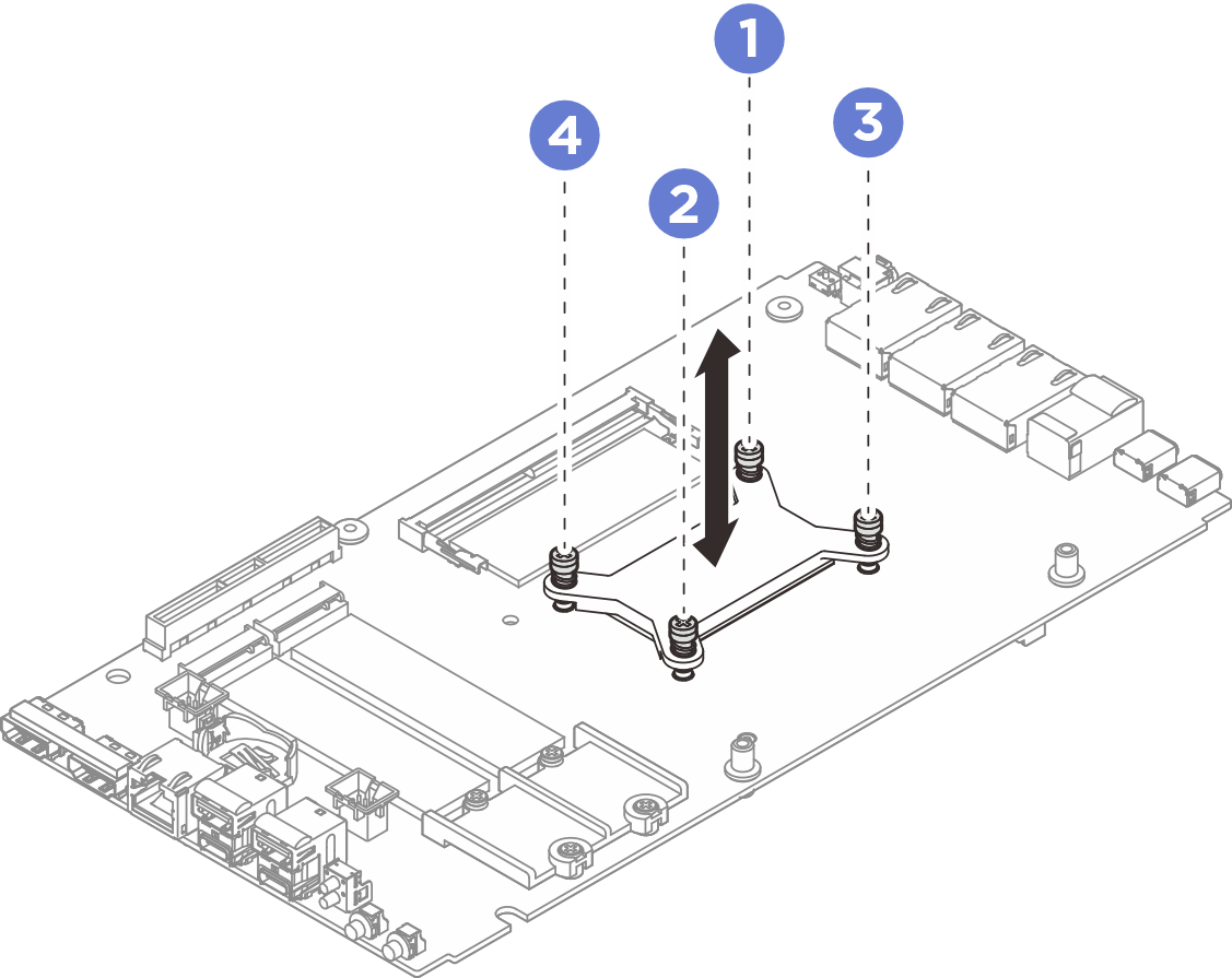
- Follow the screw sequence
After you finish
Install a replacement unit. See Install the processor heat sink.
If you are instructed to return the component or optional device, follow all packaging instructions, and use any packaging materials for shipping that are supplied to you.
Demo video