Thermal pad installation guidelines
Follow the information in this section to identify the shape, location, orientation and installation procedure of the thermal pads.
- If a thermal pad is in any of the following conditions, replace the thermal pad with a new one.
- The thermal pad is damaged or detached from the surface.
- The new part to be installed is of different brand or form factor from the replaced one; the new part might cause thermal pads to be deformed or damaged.
- Before replacing the thermal pad, gently clean the interface plate and the hardware surface with an alcohol cleaning pad.
- Hold the thermal pad carefully to avoid deformation. Make sure no screw hole or opening is blocked by the thermal pad.
- Do not use expired thermal pads. Check the expiry date (1 year after the manufacturing date) on the thermal pad package. If the thermal pads are expired, order new thermal pads for proper replacement.
Thermal pad identification and location
Thermal pads on top cover (including top cover thermal pad kit and CPU thermal pad)
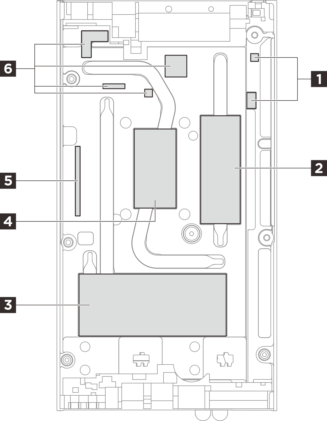 | ||
| Pad index | Replaceable component touching the pad | Pad orientation |
| 1 | N/A | Pink side facing outward |
| 2 | Memory module in DIMM slot 1 | Pink side facing outward |
| 3 | M.2 drives in slot 2 and slot 3 | Pink side facing outward |
| 4 | CPU Note CPU thermal pad is an independent part, not included in top cover thermal pad kit. | Glossy side facing outward |
| 5 | N/A | Pink side facing outward |
| 6 | N/A | Pink side facing outward |
Bottom cover thermal pad kit
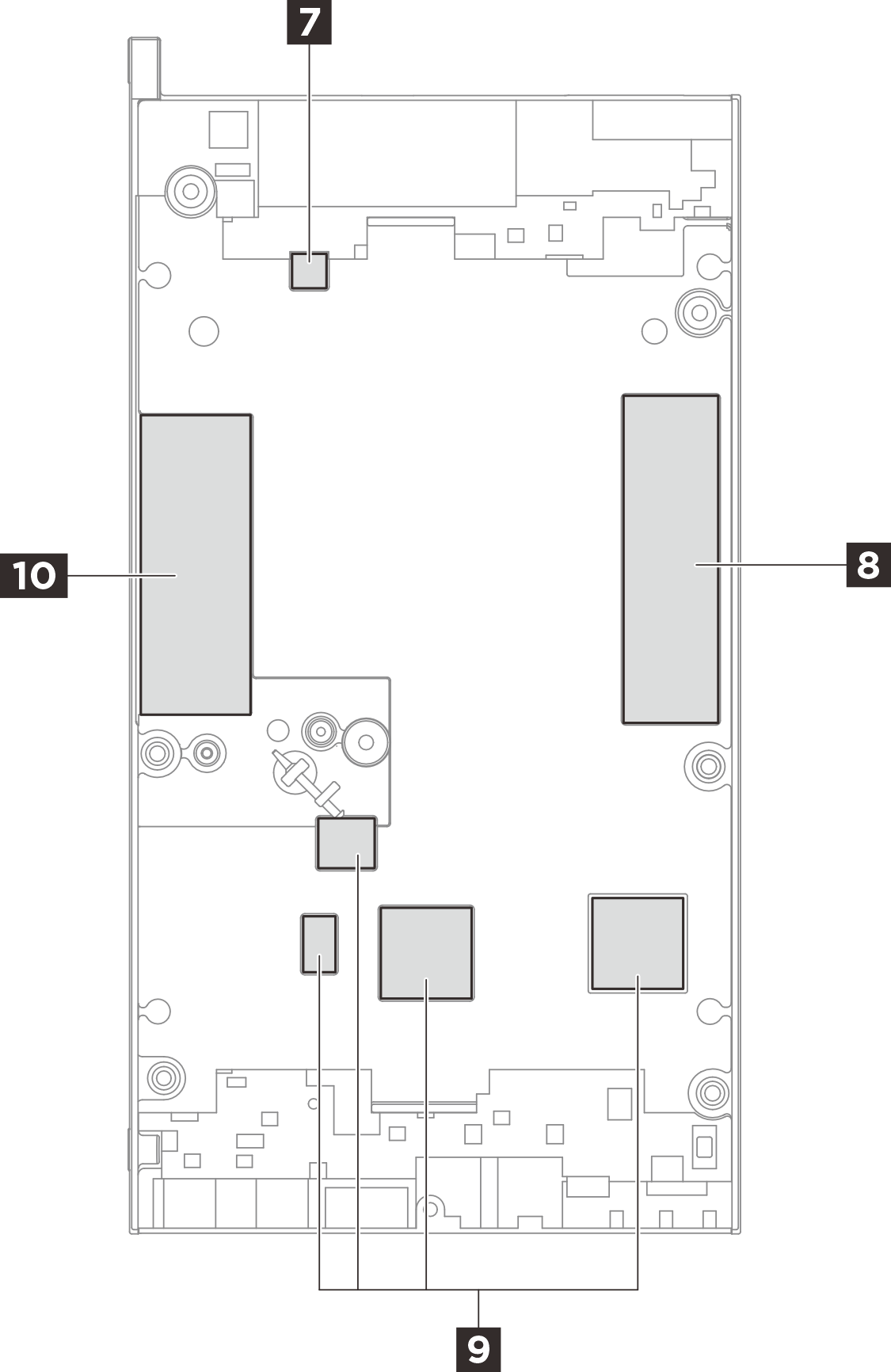 | ||
| Pad index | Replaceable component touching the pad | Pad orientation |
| 7 | N/A | Pink side facing outward |
| 8 | M.2 drive in slot 1 | Pink side facing outward |
| 9 | N/A | Pink side facing outward |
| 10 | Memory module in DIMM slot 2 | Pink side facing outward |
System board thermal pad kit
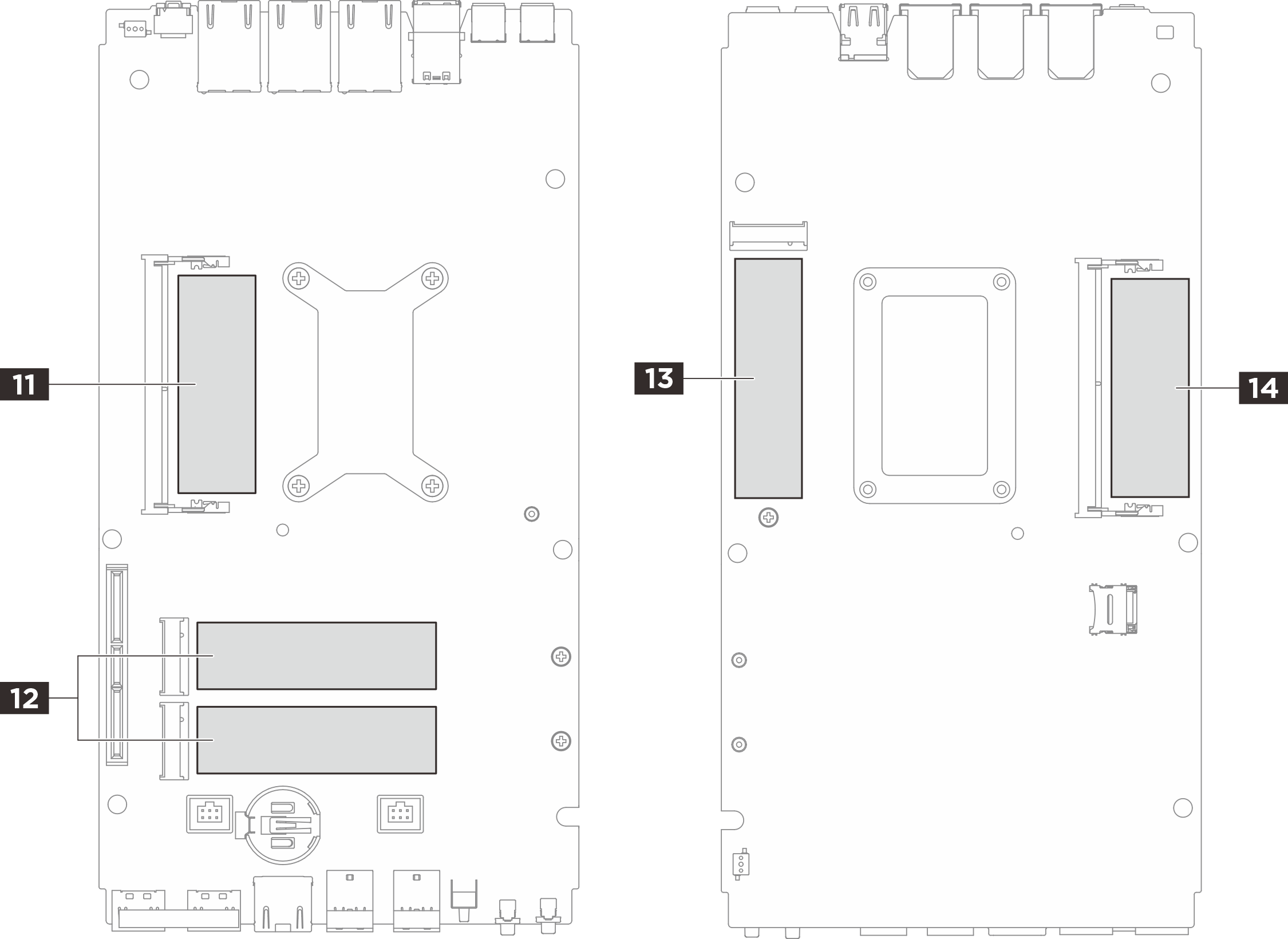 | ||
| Pad index | Replaceable component touching the pad | Pad orientation |
| 11 | Memory module in DIMM slot 1 | Pink side facing outward |
| 12 | M.2 drives in slot 2 and slot 3 | Pink side facing outward |
| 13 | M.2 drive in slot 1 | Pink side facing outward |
| 14 | Memory module in DIMM slot 2 | Pink side facing outward |
Thermal pad installation procedure
Thermal pad installation procedure
11 14 Memory module thermal pad on system board:
Peel off the transparent plastic film on the gray side of the pad, and attach the thermal pad to the surface.
Remove the liner from the ESD absorbent pad, and align the ESD absorbent pad with the thermal pad; then, stick the ESD absorbent pad to the thermal pad.
4 CPU thermal pad:
Peel off the transparent plastic film from the pad, and attach the thermal pad to the top cover.
Remove the other plastic film from the pad.
Thermal pads except for 4 11 14:
Peel off the transparent plastic film on the gray side of the pad, and attach the thermal pad to the surface.
Remove the other plastic film from the pad.