Install a node to the DIN rail
Follow instructions in this section to install a node into a node sleeve, as well as install a node sleeve to the DIN-rail.
About this task
To avoid potential danger, make sure to read and follow the safety information.
- S002
 CAUTIONThe power-control button on the device and the power switch on the power supply do not turn off the electrical current supplied to the device. The device also might have more than one power cord. To remove all electrical current from the device, ensure that all power cords are disconnected from the power source.
Read Installation Guidelines and Safety inspection checklist to make sure that you work safely.
Make sure that all components and cables are installed and seated correctly inside the node, except for the power cords and external cables, and that no loose tools or parts are left inside the node.
Reserve 500 mm of clearance in front of the node for the procedures of removal or installation.
This section includes the following procedures:
Install the node sleeve to the DIN rail
Procedure
- Install the two DIN-rail clips onto the node sleeve.
- Insert and tighten the four screws as shown.Figure 1. Installation of the DIN-rail clips to the node sleeve
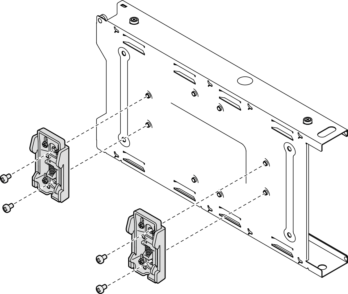
- Insert and tighten the four screws as shown.
- Install the node sleeve onto the DIN rail.
- Hook the DIN-rail clips on the back of the node sleeve onto the DIN rail at an angle as shown.Figure 2. Installation of the DIN-rail clips to the DIN rail
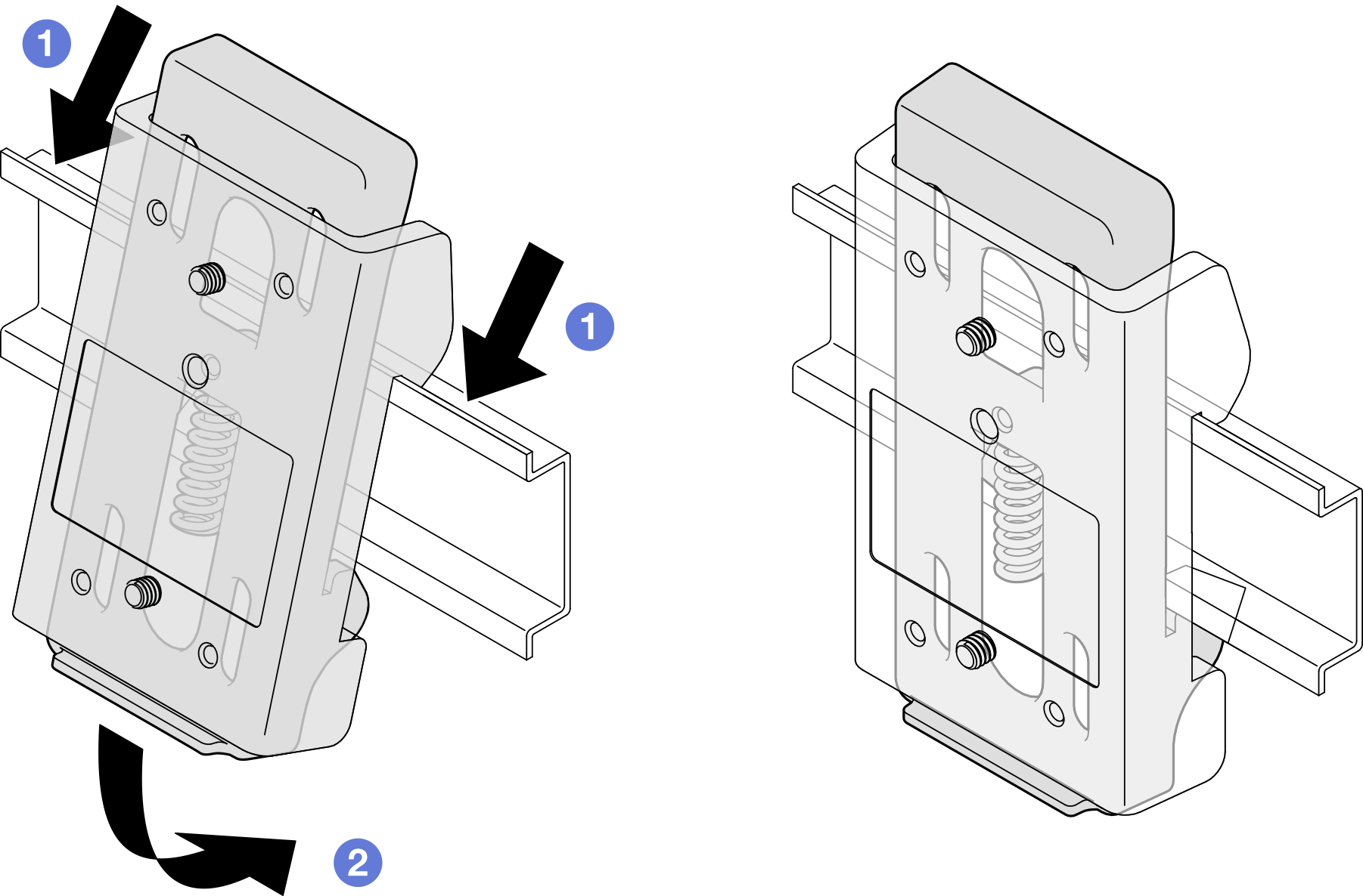
- Push down the node sleeve at an angle as shown to ensure that the DIN-rail clips on the back of the node sleeve are securely seated.Figure 3. Installation of the node sleeve to the DIN rail
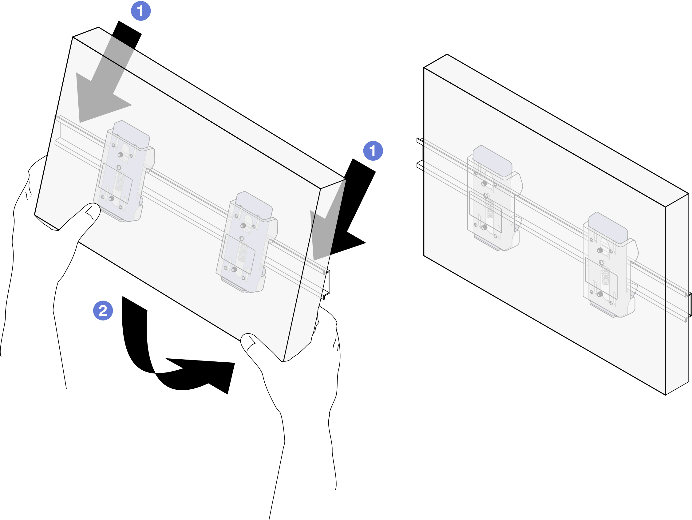
- Hook the DIN-rail clips on the back of the node sleeve onto the DIN rail at an angle as shown.
After this task is completed
If necessary, proceed to install a node into the node sleeve (see Install a node into the node sleeve).
Install a node into the node sleeve
Depending on the specific configuration, the node or security bezel might look different from the illustrations in this section.
Procedure
- Install the node into the node sleeve.
 Align the node with the node sleeve; then, insert and slide the node into place.
 Tighten the two thumbscrews on the side of the node sleeve.Figure 4. Installation of a node into a node sleeve
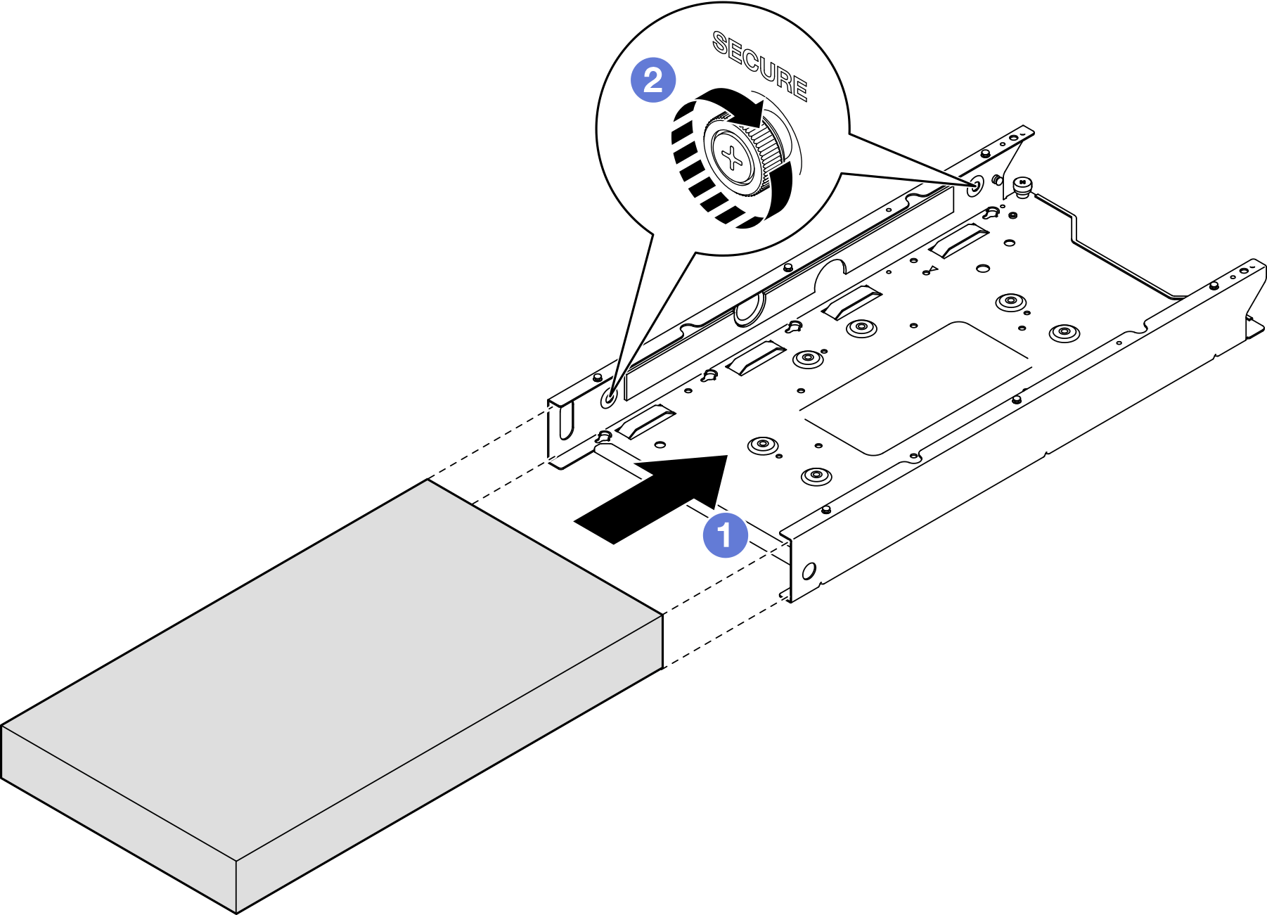
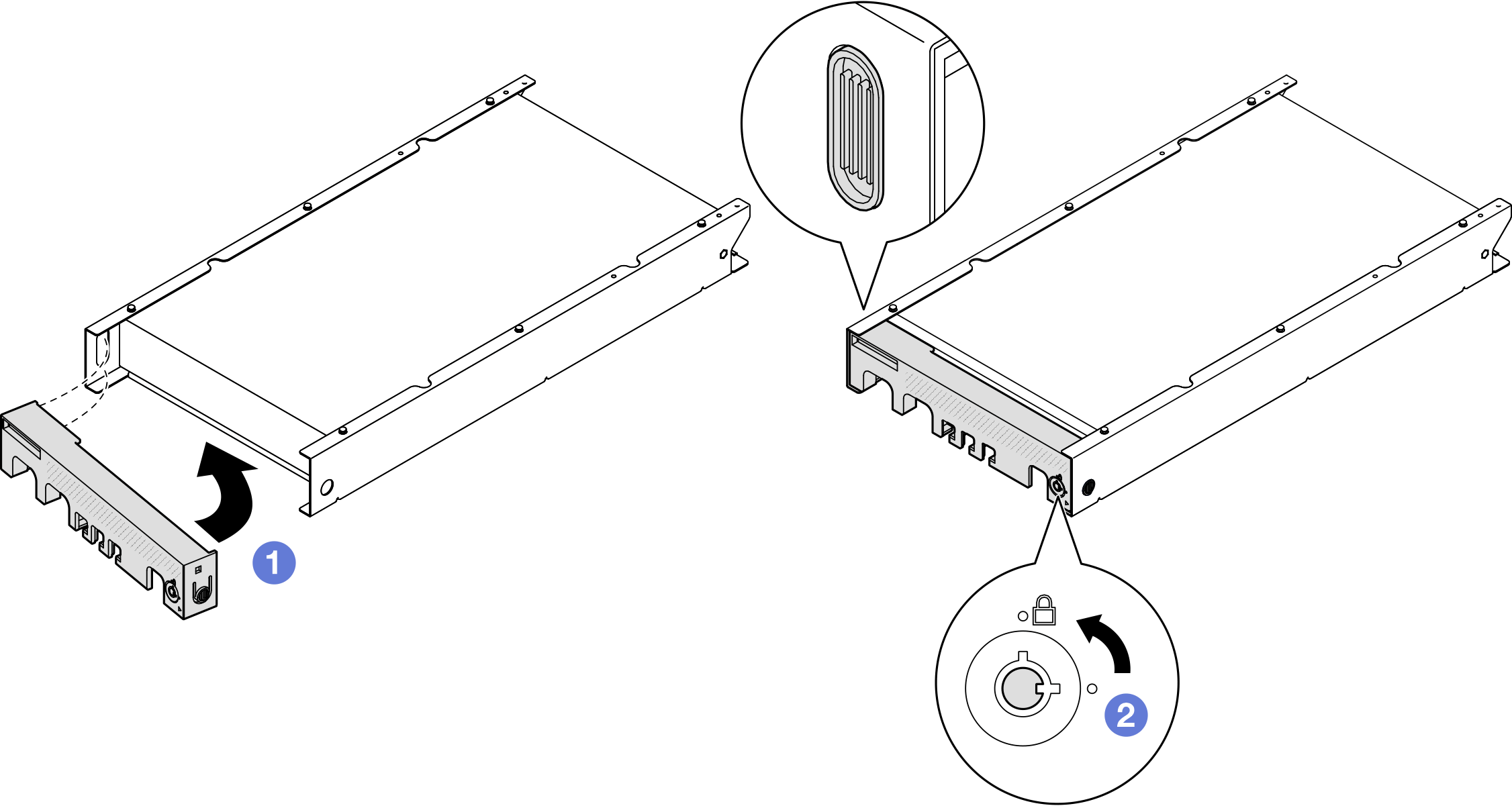
- (Optional) If necessary, install a security bezel to the node sleeve.Note
- If necessary, do the following BEFORE installing the security bezel:
Connect the power cords and power on the server (see Power on the server).
Connect all the external cables.
- Insert the tab on the security bezel into the slot; then, pivot the security bezel inward until the other side of the bezel clicks into place.
- Use the key to lock the security bezel.Figure 5. Installation of a security bezel onto a node sleeve
After this task is completed
Proceed to complete the parts replacement (see Complete the parts replacement).