Install the drive cage and trayless drives
See this topic to learn how to install the drive cage and trayless drives.
About this task
The server supports the following trayless drives:
Four 7mm SAS/SATA/NVMe trayless drives
Table 1. Drive bay and PCIe slot numbering with 7mm drives PCIe slot 7
(OCP 3.0)
Riser 1 PCIe slot 5 Riser 2 PCIe slot 2 PCIe slot 1 and 2
(M.2 Bay 0 and 1)
PCIe slot 6 PCIe slot 3 Drive 2 Drive 3 Drive 0 Drive 1 Two 15mm SAS/SATA/NVMe trayless drives
Table 2. Drive bay and PCIe slot numbering with 15mm drives PCIe slot 7
(OCP 3.0)
Riser 1 PCIe slot 5 Riser 2 PCIe slot 2 PCIe slot 1 and 2
(M.2 Bay 0 and 1)
PCIe slot 6 PCIe slot 3 Drive 0 Drive 1
Start with the topic corresponding to the planned configuration:
Install the 7mm trayless drives
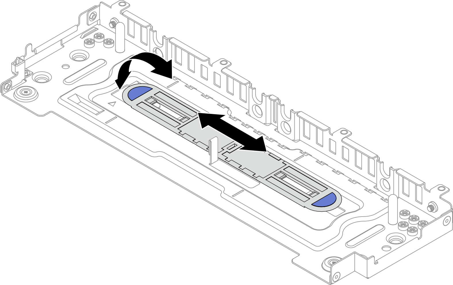
- If the spacer is store on the bottom of the drive cage, slide it left slightly to disengage and remove it from the drive cage.Figure 1. Disengaging the drive spacer
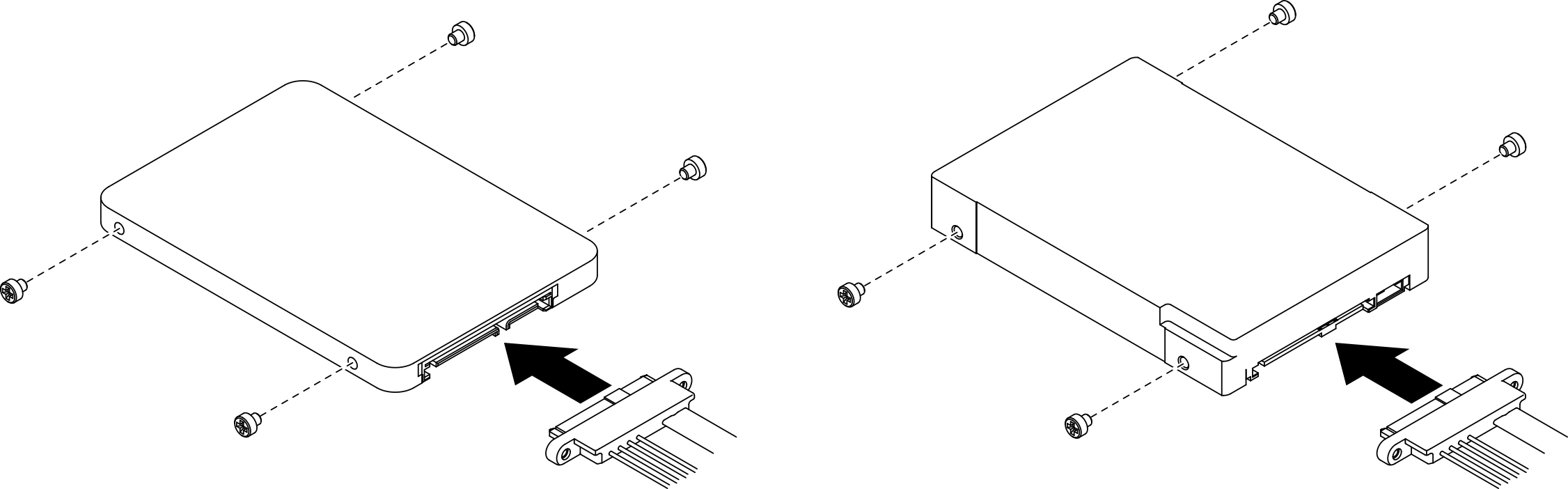
- Install four screws on each of the drives, and connect the cables to the drives according to the cable routing plan.Figure 2. Installing screws and connecting drive cables
 Note16 spared screws are kept on the drive cage as illustrated.Figure 3. Spared screws on the drive cage
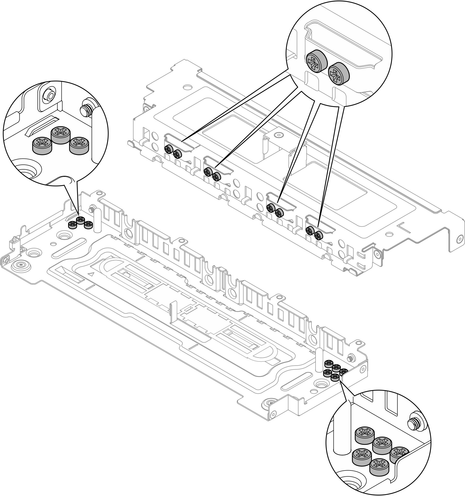
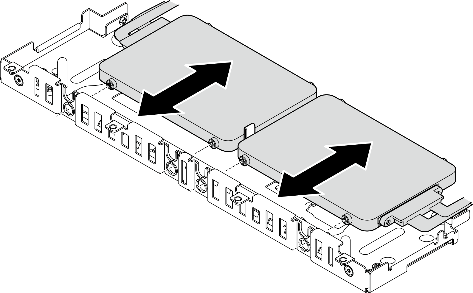
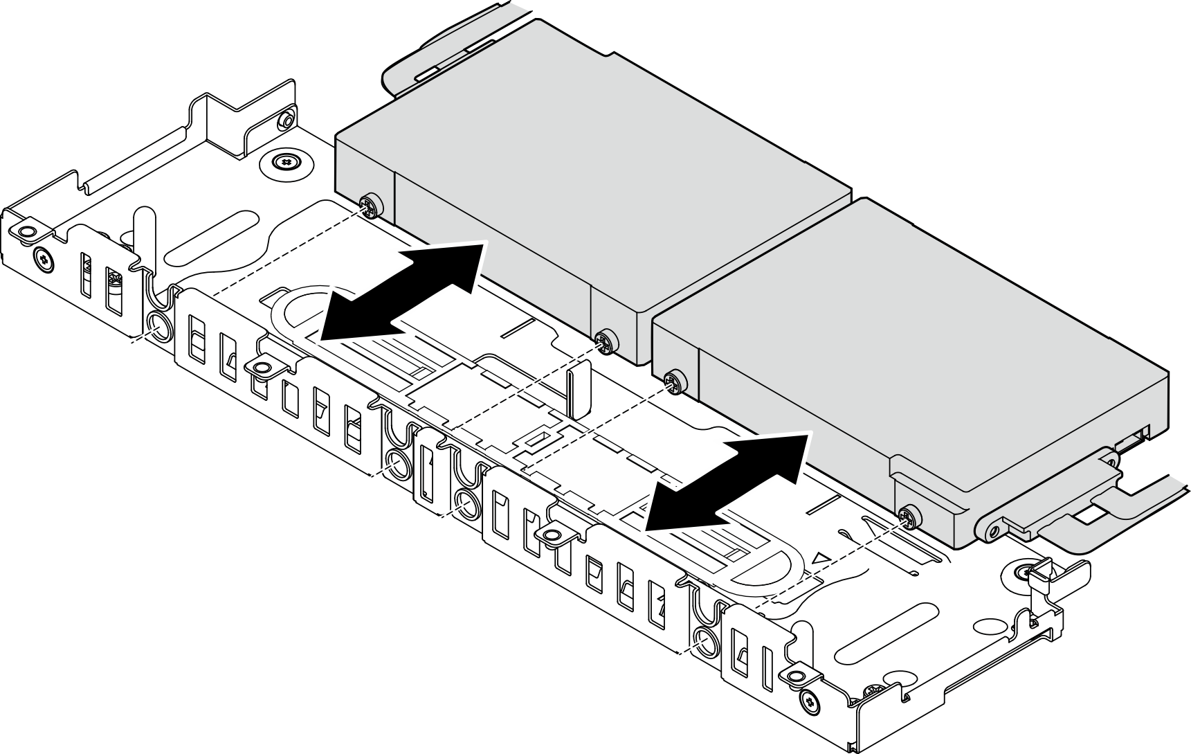
- Align the screws on the two drives with the slots on the drive cage, and slide the drives in until the screws are secured in the slots.Figure 4. Installing the lower 7mm trayless drives
- Align the slot in the middle of the drive spacer to the guiding pin in the drive cage, and place the spacer on top of the two drives.Figure 5. Placing the drive spacer
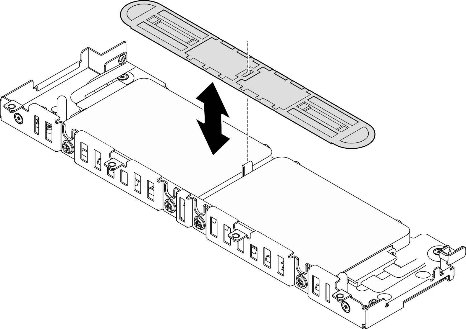
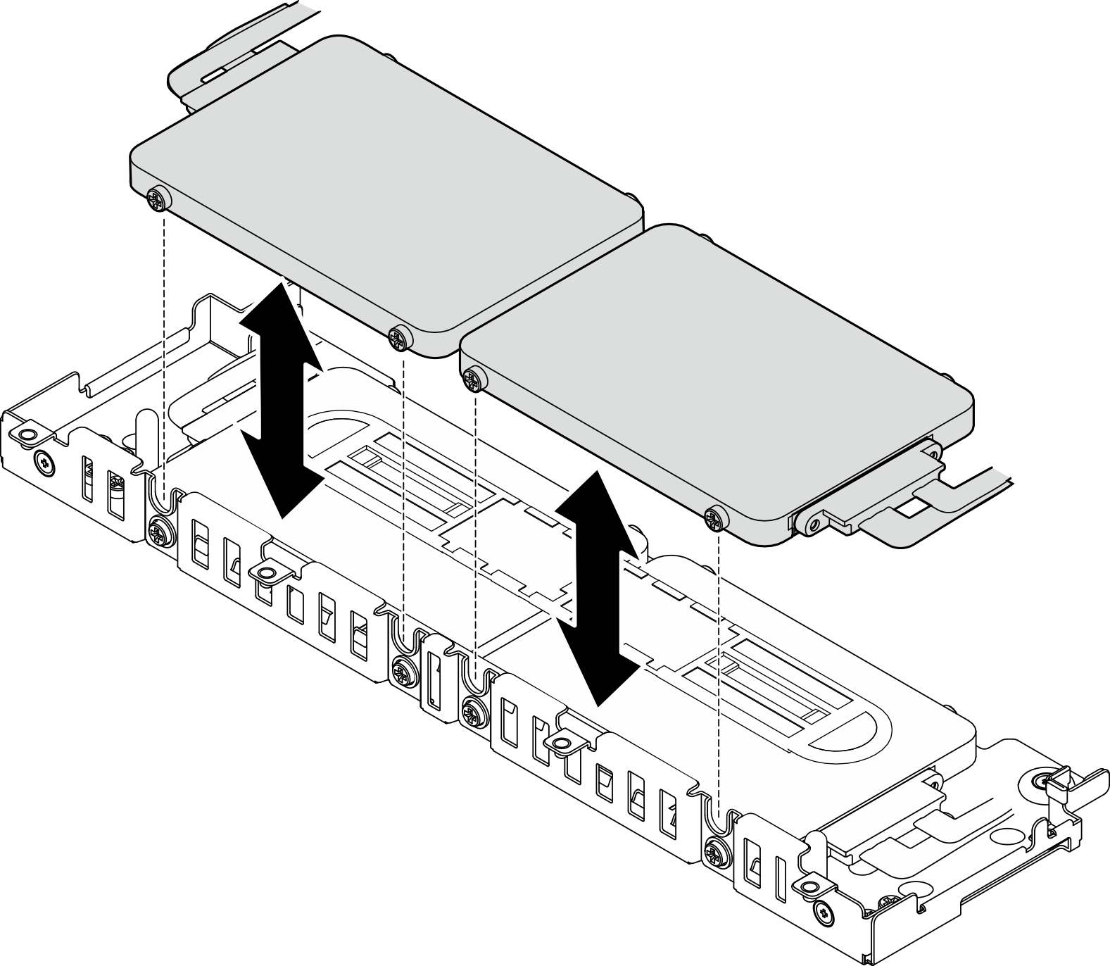
- Align the screws on the two upper drives with the slots on the drive cage, and lower the drives until the screws are secured in the slots.Figure 6. Installing the upper 7mm trayless drives
Install the 15mm trayless drives
- Install four screws on each of the drives, and connect the cables to the drives according to the cable routing plan.Figure 7. Installing screws and connecting drive cablesNote16 spared screws are kept on the drive cage as illustrated.Figure 8. Spared screws on the drive cage
- Align the screws on the two drives with the slots on the drive cage, and slide the drives in until the screws are secured in the slots.Figure 9. Installing 15mm trayless drives
 NoteWhen the system comes with one or three drives, make sure the unused cable connector is secured with the cable band as illustrated.Figure 10. Cable band for 1 or 3 drive configuration
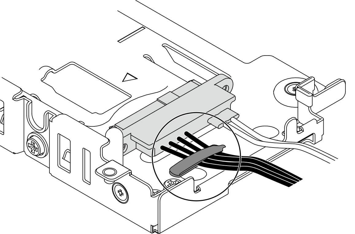
Install the drive cage
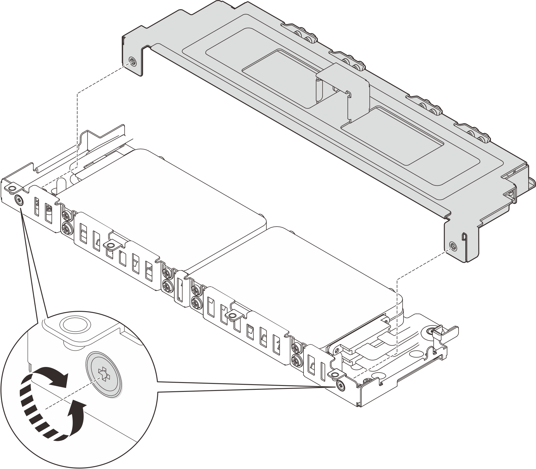
- Align the captive screws on the cover with screw holes on the drive cage, and tighten the captive screws to secure the cover to the cage.Figure 11. Installing the drive cage cover
- If applicable, contain cables to the side cable clips on the drive cage. If there are power and signal cables. make sure to contain power cables first.Figure 12. Routing cables through the drive cage cable clips
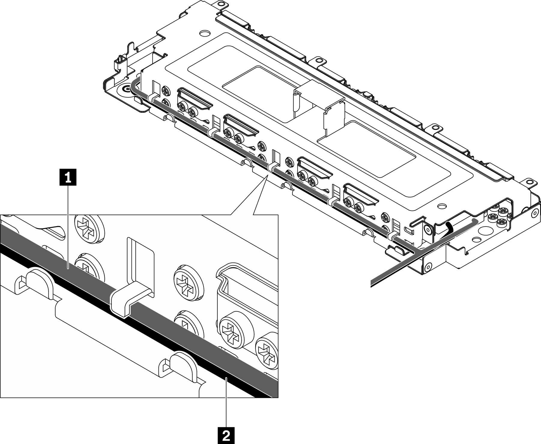
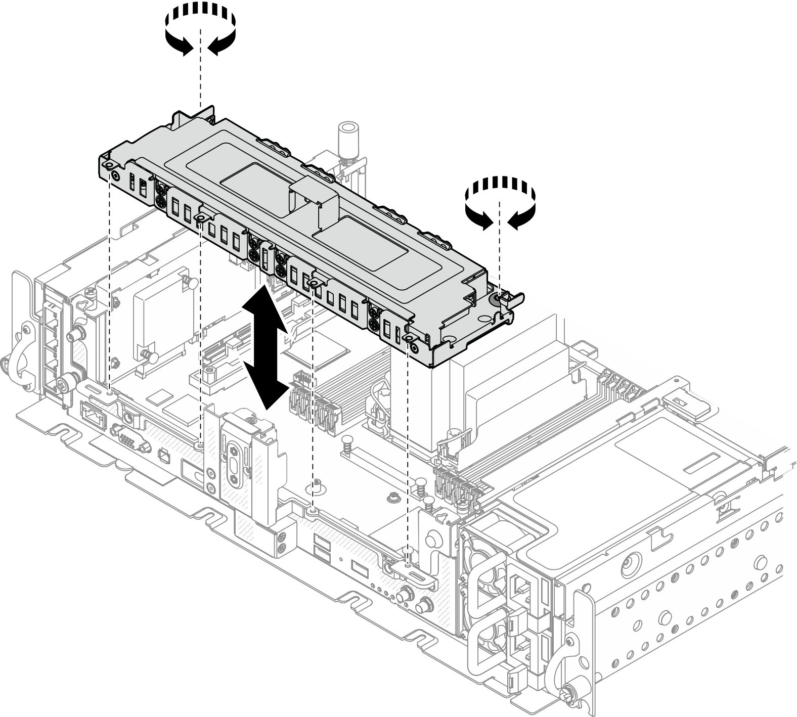
1 Signal cable 2 Power cable - Align the tabs on the drive cage with the guide pins on the chassis, and lower the drive cage; then, tighten the two captive screws to secure the drive cage.Figure 13. Installing the drive cage
After this task is completed
Make sure the cables are connected based on the cable routing plans (see Cable routing for trayless drives).
Proceed to complete the parts replacement (see Complete the parts replacement).
Give documentation feedback