Install a 2.5-inch drive backplane
Use this information to install a 2.5-inch drive backplane.
Before you install a 2.5-inch drive backplane:
Read Installation Guidelines to ensure that you work safely.
- If the compute node is installed in a chassis, remove it (see Remove a compute node for instructions).
- Carefully lay the compute node on a flat, static-protective surface, orienting the compute node with the bezel pointing toward you.
Remove the compute node cover (see Remove the compute node cover for instructions).
Note
Several different types of drive backplanes can be installed in the compute node. All are removed and installed in a similar manner.
SATA backplane
NVMe/(SATA) backplane
SAS/SATA backplane
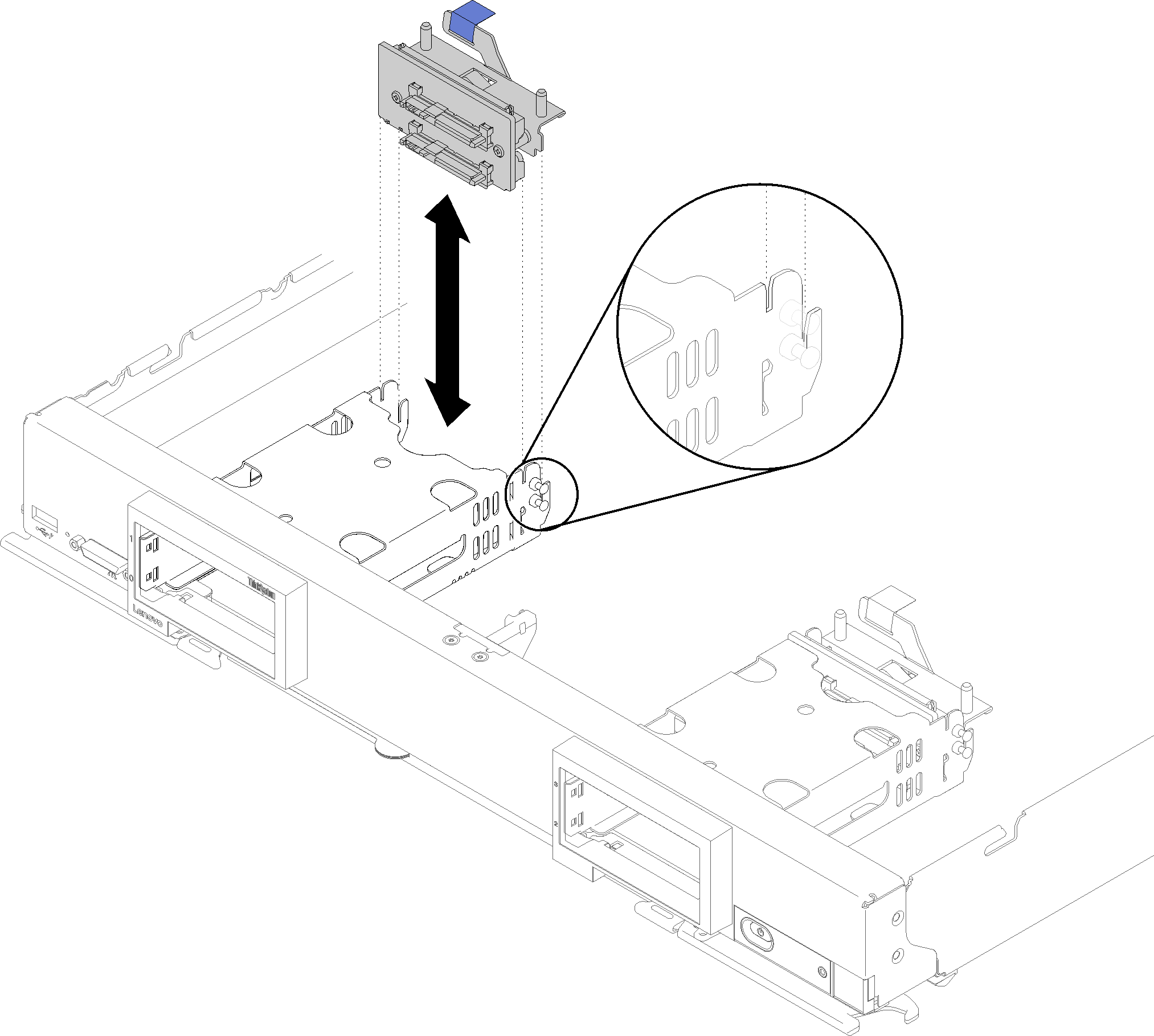
To install a 2.5-inch drive backplane, complete the following steps:
Figure 1. 2.5-inch drive backplane installation
After you install the drive backplane, complete the following steps:
- Install the compute node cover onto the compute node (see Install the compute node cover for instructions).
- Install the compute node into the chassis (see Install a compute node for instructions).
Demo video
Give documentation feedback