Front I/O module cable routing
Use the section to understand the cable routing for the front I/O module.
Note
Connections between connectors; 1↔1, 2↔2, 3↔3, ... n↔n
When routing the cables, ensure that all cables are routed appropriately through the cable guides and cable clips.
3.5-inch model
Figure 1. Front I/O module cable routing for 3.5-inch model
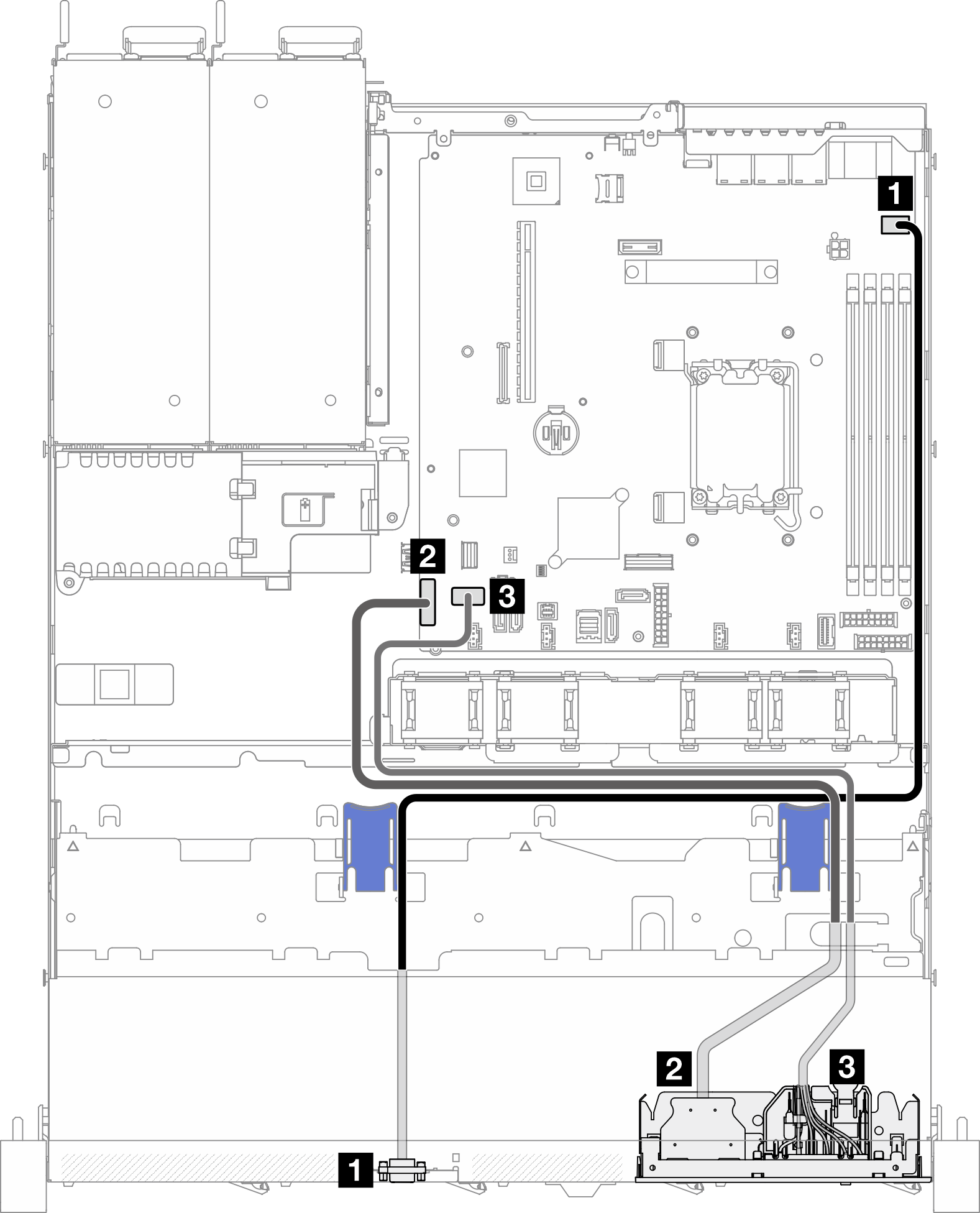
| From | To |
|---|---|
| 1 Front VGA | System board: Front VGA connector |
| 2 Front USB 3.0/2.0 | System board: Front USB 3.0/2.0 header (DCI support) |
| 3 Front I/O module | System board: Front I/O module connector |
2.5-inch model
Figure 2. Front I/O module cable routing for 2.5-inch model
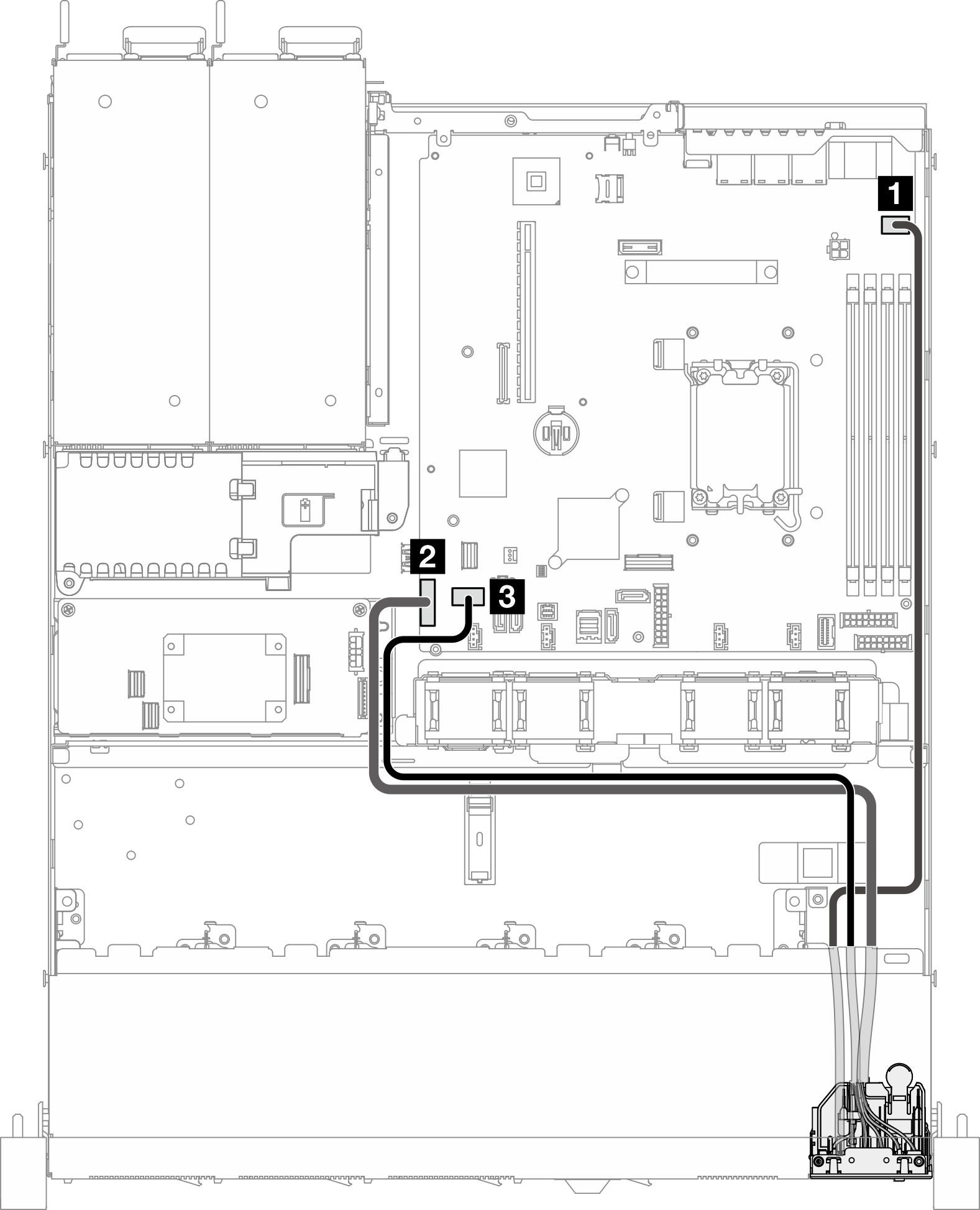
| From | To |
|---|---|
| 1 Front VGA | System board: Front VGA connector |
| 2 Front USB 3.0/2.0 | System board: Front USB 3.0/2.0 header (DCI support) |
| 3 Front I/O module | System board: Front I/O module connector |
Give documentation feedback