4 x 2.5'' NVMe backplane (one processor)
Use this section to understand the NVMe backplane cable routing for server model with four 2.5-inch front drives and one processor.
Cable routing for onboard configuration
Figure 1. Cable routing for onboard configuration of 4 x 2.5-inch front NVMe drives
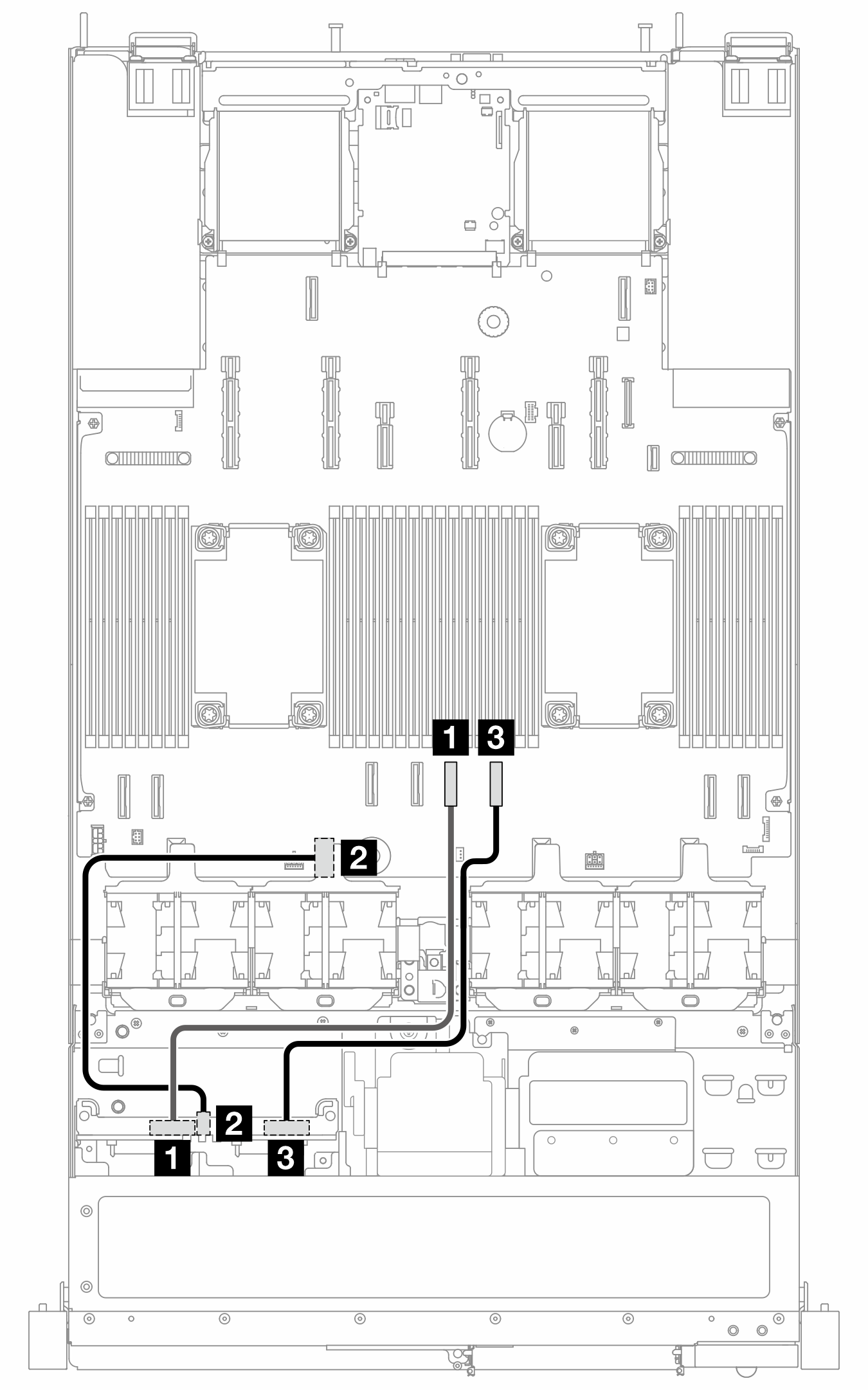
| From | To |
|---|---|
| 1 NVMe 0–1 | 1 PCIe 4 |
| 2 Power | 2 Power connector 2_A |
| 3 NVMe 2–3 | 3 PCIe 3 |
Give documentation feedback