Memory module installation rules
Memory modules must be installed in a specific order based on the memory configuration that you implement on your server.
Minimum: 8 GB
Maximum: 2 TB
Type (depending on the model):
TruDDR4 2933, single-rank or dual-rank, 8 GB/16 GB/32 GB/64 GB RDIMM
TruDDR4 3200, dual-rank, 16 GB/32 GB/64 GB RDIMM
TruDDR4 2933, quad-rank, 128 GB 3DS RDIMM
TruDDR4 3200, quad-rank, 128 GB 3DS RDIMM (Only 7003 series processors are supported.)
Memory modules in your server must be the same type.
Memory modules from different vendors are supported.
Memory modules with different capacities are supported. Install the memory module that has the higher capacity first.
Memory modules with different ranks are supported. Install the memory module with the highest rank first.
Do not mix x4 and x8 DIMMs in the same channel.
- DIMMs of 3200 MHz and 2933 MHz are supported:
2933 MHz DIMMs: operate at 2933 MHz for both 1 DIMM per channel and 2 DIMMs per channel
3200 MHz DIMMs: operate at 3200 MHz when 1 DIMM per channel, but operate at 2933 MHz when 2 DIMMs per channel
Mixing of 2933 MHz and 3200 MHz DIMMs are supported in different channels, operating at 2933 MHz.
NoteOperating speed depends on the processor model. If the processor only supports a memory bus speed of 2666 MHz, all the installed DIMMs operate at 2666 MHz. Install a memory module filler if there is no memory module installed in the slot.
| Unified Memory Controller (UMC) | UMC2 | UMC3 | UMC1 | UMC0 | UMC6 | UMC7 | UMC5 | UMC4 | ||||||||
| Channel (CH) | D | C | B | A | E | F | G | H | ||||||||
| CH slot | 1 | 0 | 1 | 0 | 1 | 0 | 1 | 0 | 0 | 1 | 0 | 1 | 0 | 1 | 0 | 1 |
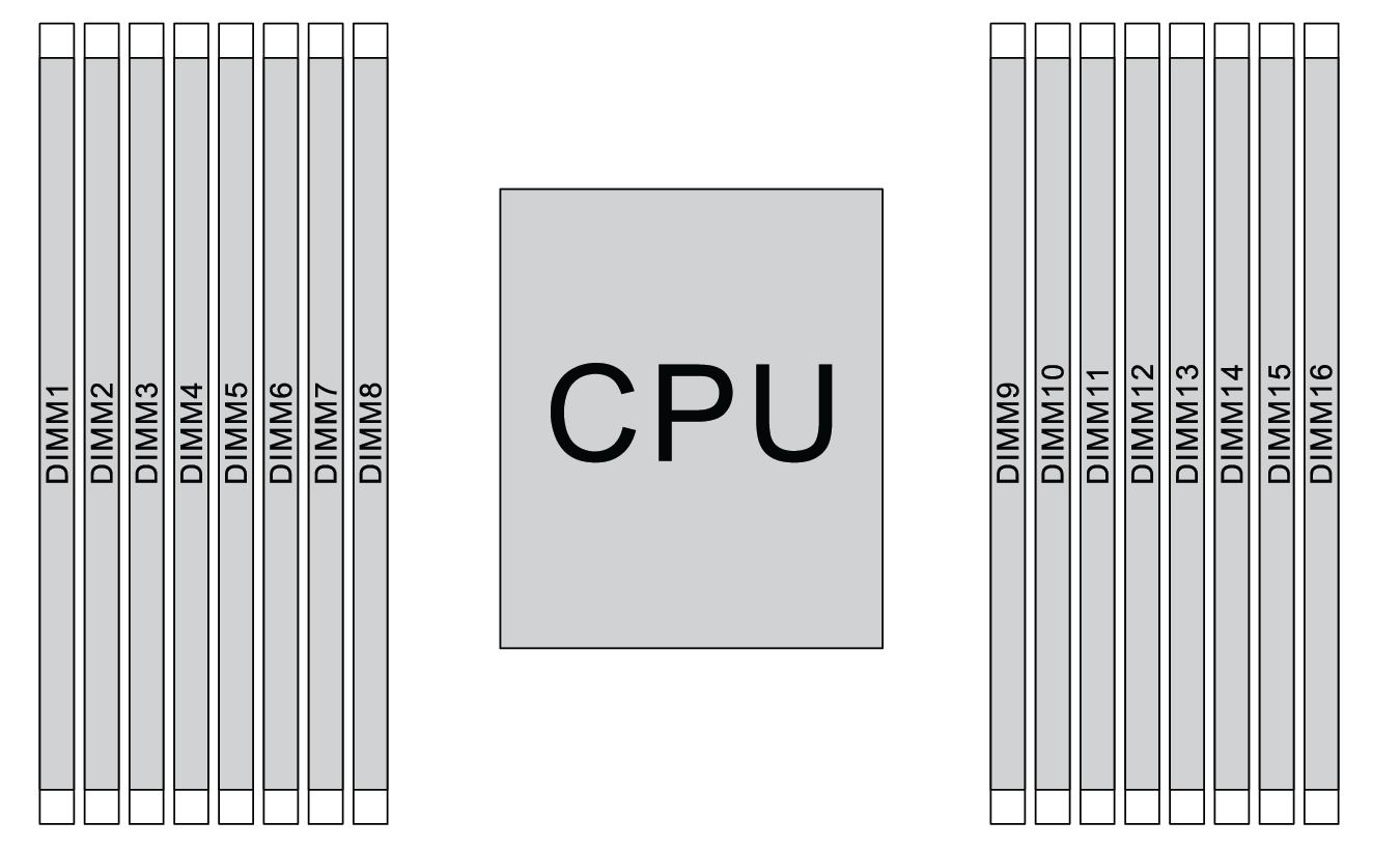
| DIMM number | 1 | 2 | 3 | 4 | 5 | 6 | 7 | 8 | 9 | 10 | 11 | 12 | 13 | 14 | 15 | 16 |
| 1 DIMM | 3 | |||||||||||||||
| 2 DIMMs | 1 | 3 | ||||||||||||||
| 3 DIMMs | 1 | 3 | 14 | |||||||||||||
| 4 DIMMs | 1 | 3 | 14 | 16 | ||||||||||||
| 5 DIMMs | 1 | 3 | 7 | 14 | 16 | |||||||||||
| 6 DIMMs | 1 | 3 | 5 | 7 | 14 | 16 | ||||||||||
| 7 DIMMs | 1 | 3 | 5 | 7 | 10 | 14 | 16 | |||||||||
| 8 DIMMs | 1 | 3 | 5 | 7 | 10 | 12 | 14 | 16 | ||||||||
| 9 DIMMs | 1 | 3 | 4 | 5 | 7 | 10 | 12 | 14 | 16 | |||||||
| 10 DIMMs | 1 | 2 | 3 | 4 | 5 | 7 | 10 | 12 | 14 | 16 | ||||||
| 11 DIMMs | 1 | 2 | 3 | 4 | 5 | 7 | 10 | 12 | 13 | 14 | 16 | |||||
| 12 DIMMs | 1 | 2 | 3 | 4 | 5 | 7 | 10 | 12 | 13 | 14 | 15 | 16 | ||||
| 13 DIMMs | 1 | 2 | 3 | 4 | 5 | 7 | 8 | 10 | 12 | 13 | 14 | 15 | 16 | |||
| 14 DIMMs | 1 | 2 | 3 | 4 | 5 | 6 | 7 | 8 | 10 | 12 | 13 | 14 | 15 | 16 | ||
| 15 DIMMs | 1 | 2 | 3 | 4 | 5 | 6 | 7 | 8 | 9 | 10 | 12 | 13 | 14 | 15 | 16 | |
| 16 DIMMs | 1 | 2 | 3 | 4 | 5 | 6 | 7 | 8 | 9 | 10 | 11 | 12 | 13 | 14 | 15 | 16 |
| DIMM Qty | DIMM population order |
| 6 | 1, 3, 7, 10, 14, 16 |
| 12 | 1, 2, 3, 4, 7, 8, 9, 10, 13, 14, 15, 16 |