Install the 2.5-inch front drive backplane
Use this information to install the 2.5-inch front drive backplane.
About this task
2.5-inch SAS/SATA 8-bay backplane
2.5-inch AnyBay 8-bay backplane
2.5-inch NVMe 8-bay backplane
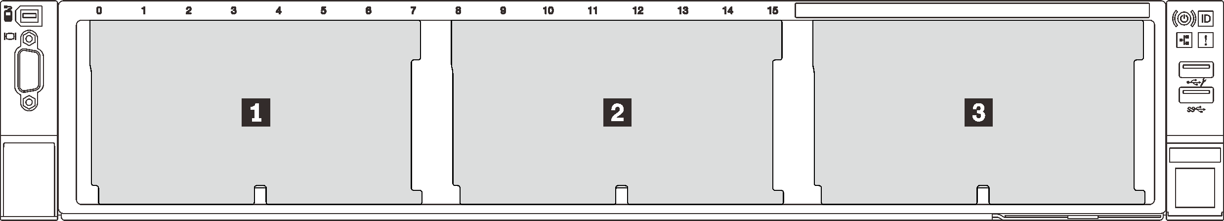
| Backplane quantity | Backplane 1 | Backplane 2 | Backplane 3 |
| 1 |
| ||
| 2 | SAS/SATA 8-bay | SAS/SATA 8-bay | |
SAS/SATA 8-bay |
| ||
AnyBay 8-bay | NVMe 8-bay | ||
NVMe 8-bay | NVMe 8-bay | ||
| 3 | SAS/SATA 8-bay | SAS/SATA 8-bay | SAS/SATA 8-bay |
SAS/SATA 8-bay | SAS/SATA 8-bay |
| |
SAS/SATA 8-bay | NVMe 8-bay | NVMe 8-bay | |
NVMe 8-bay | NVMe 8-bay | NVMe 8-bay |
Read Installation Guidelines to ensure that you work safely.
Power off the server and disconnect all power cords for this task.
Prevent exposure to static electricity, which might lead to system halt and loss of data, by keeping static-sensitive components in their static-protective packages until installation, and handling these devices with an electrostatic-discharge wrist strap or other grounding system.
Procedure
- Install the 2.5-inch drive front backplane.NoteDepending on the specific type, your backplane might look different from the illustration.Figure 2. 2.5-inch drive backplane installation
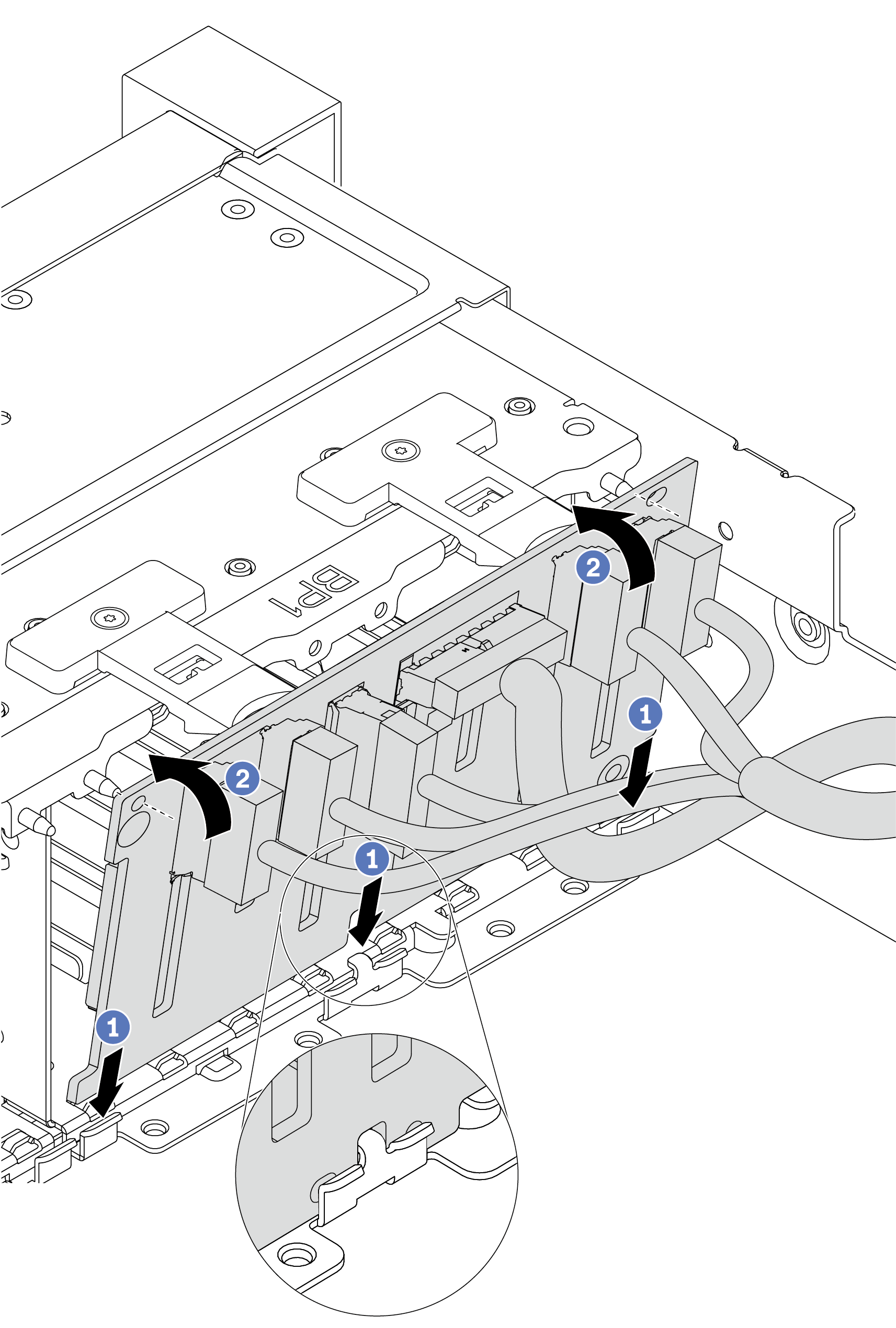
- Align the bottom of the backplane with the slots on of the chassis.
- Rotate the backplane to the vertical position and align the holes in the backplane with the pins on the chassis and press the backplane into position. The release tabs will secure the backplane in place.
After you finish
Reinstall all the drives and fillers (if any) into the drive bays. See Install a hot-swap drive.
Reinstall the fan cage. See Install the system fan cage.
Reinstall the air baffle if you have removed it. See Install the air baffle.
Complete the parts replacement. See Complete the parts replacement.
If you have installed an Anybay backplane with U.3 NVMe drives for Trimode, enable U.3 x1 mode for the selected drive slots on the backplane through the XCC Web GUI. See U.3 NVMe drive can be detected in NVMe connection, but cannot be detected in Tri-mode.
Demo video