Remove the 3.5-inch front drive backplane
Use this information to remove the 3.5-inch front drive backplane.
About this task
Read Installation Guidelines to ensure that you work safely.
Power off the server and disconnect all power cords for this task.
Prevent exposure to static electricity, which might lead to system halt and loss of data, by keeping static-sensitive components in their static-protective packages until installation, and handling these devices with an electrostatic-discharge wrist strap or other grounding system.
Before you remove or make changes to drives, drive controllers (including controllers that are integrated on the system board), drive backplanes or drive cables, back up all important data that is stored on drives.
Before you remove any component of a RAID array (drive, RAID card, etc.), back up all RAID configuration information.
If one or more NVMe solid-state drives are to be removed, it is recommended to disable them beforehand via the operating system.
Procedure
- Lift the release tabs and rotate the backplane backward slightly to release it from the two pins on the chassis.NoteDepending on the specific type, your backplane might look different from the illustration. For the 3.5-inch 12-bay backplane or the 3.5-inch 12-bay backplane with expender, some cables might need to be removed from their retaining clips or moved to the side to remove the backplane.Figure 1. 3.5-inch drive backplane removal
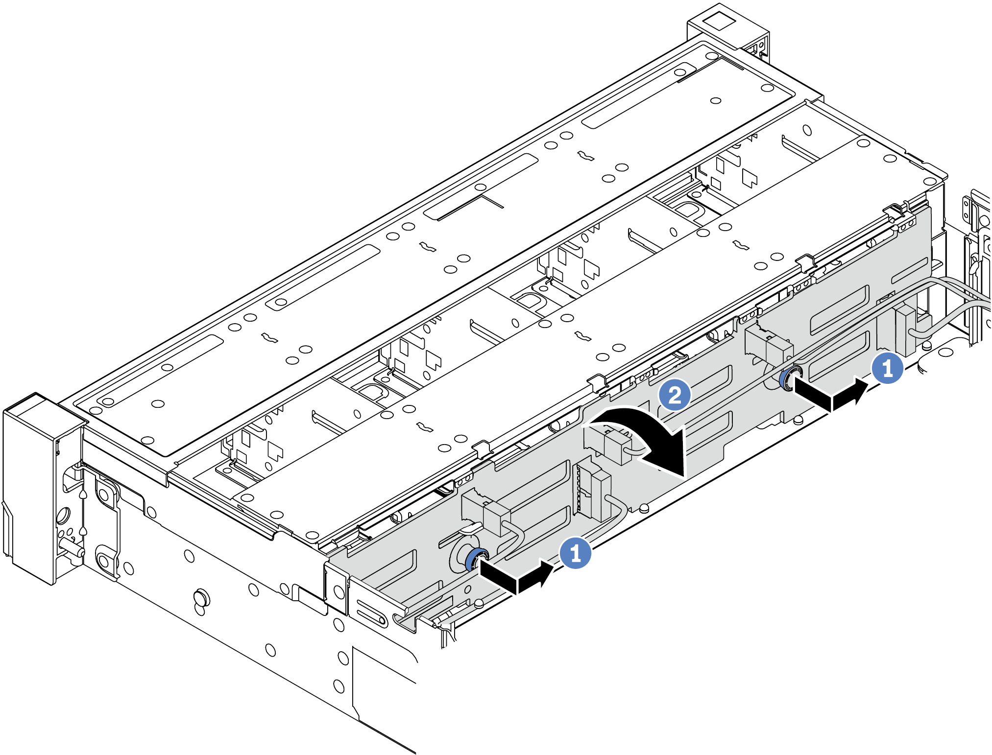
- Pull out the plungers and slightly slide the backplane to the side as shown.
- Rotate the backplane down to release it from the four hooks on the chassis. Then, carefully lift the backplane out of the chassis.
After you finish
If you are instructed to return the defective component, follow all packaging instructions and use any packaging materials that are provided.
Demo video