Server models with twenty-four 2.5-inch drives
Use this section to understand the cable routing for server models with twenty-four 2.5-inch drives.
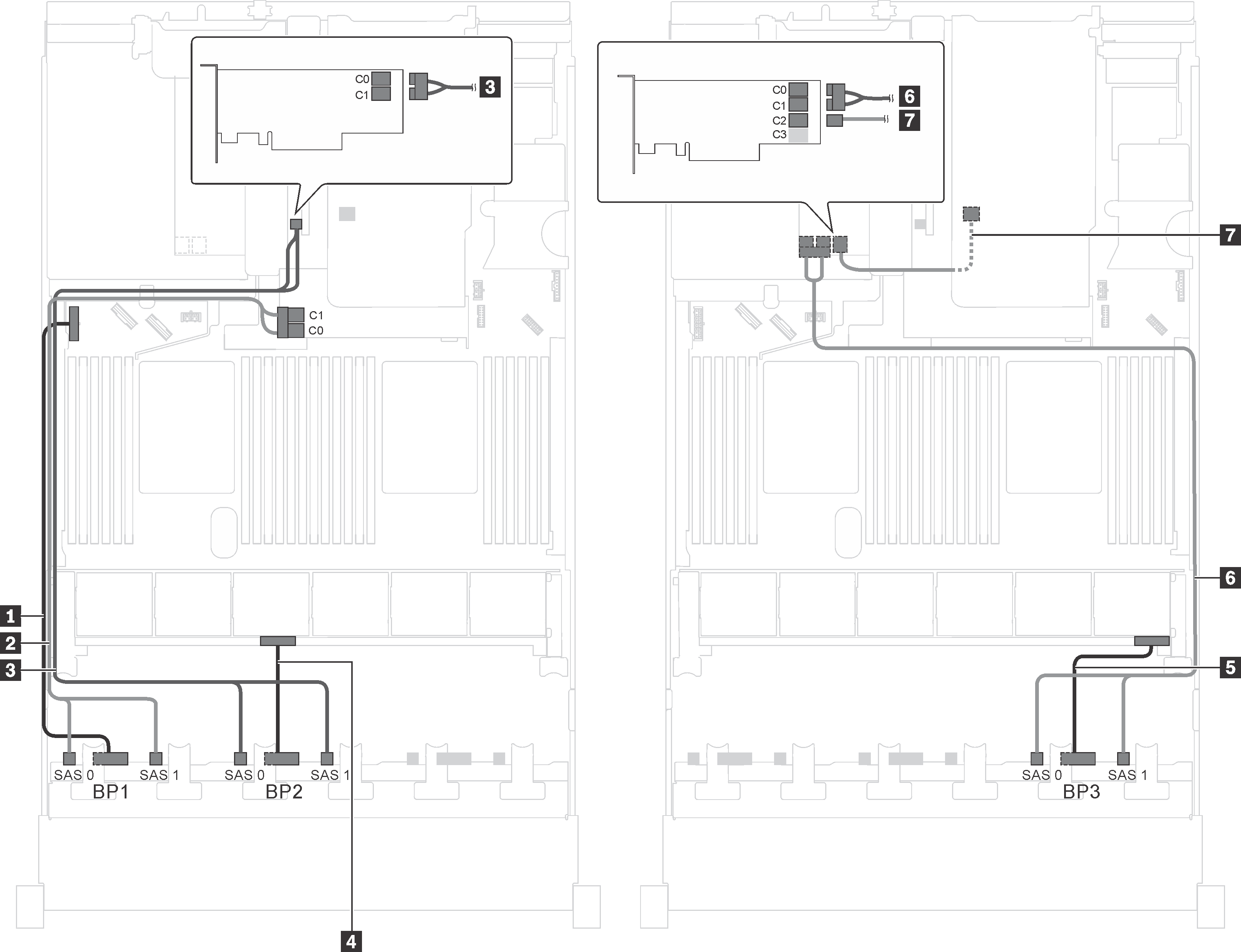
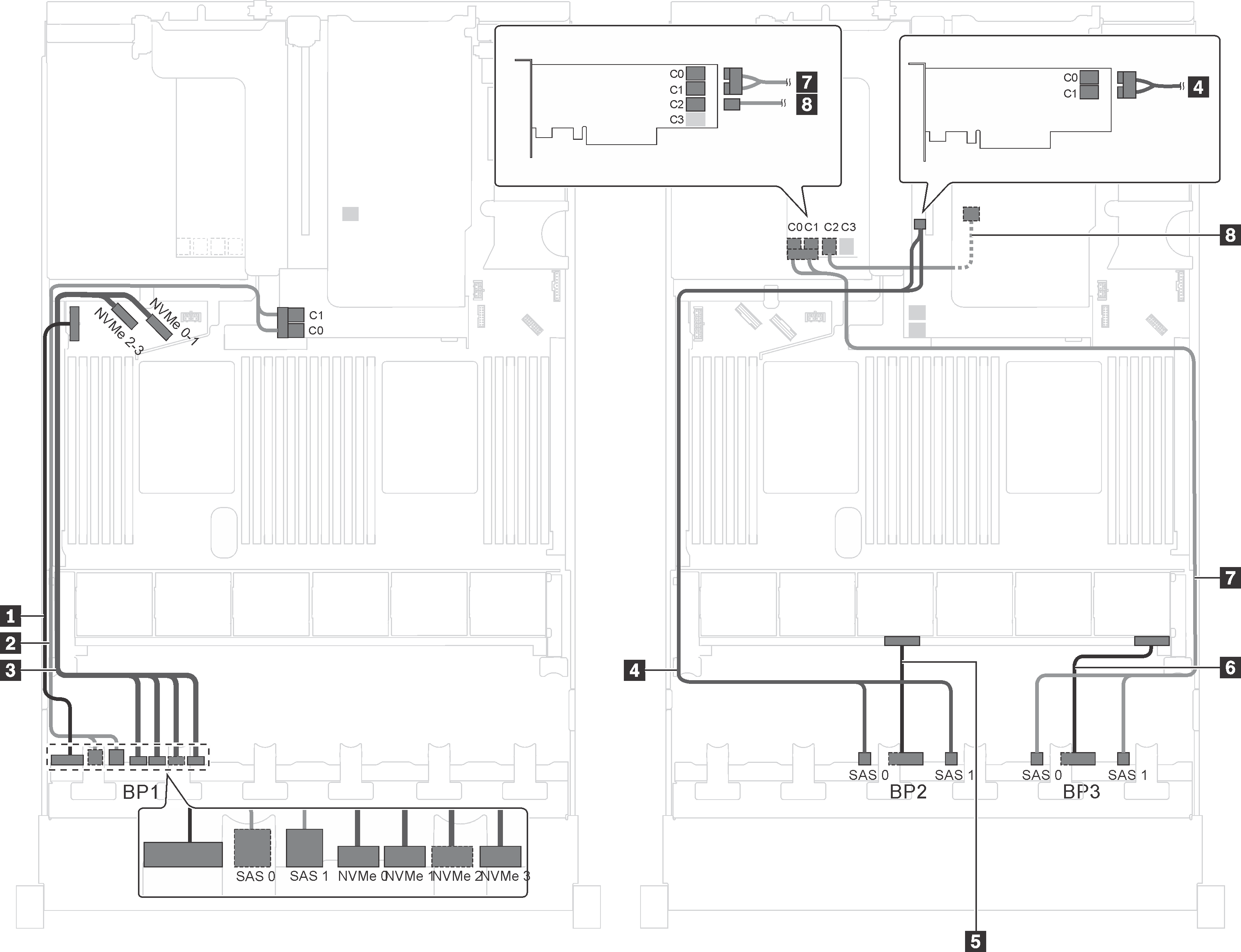
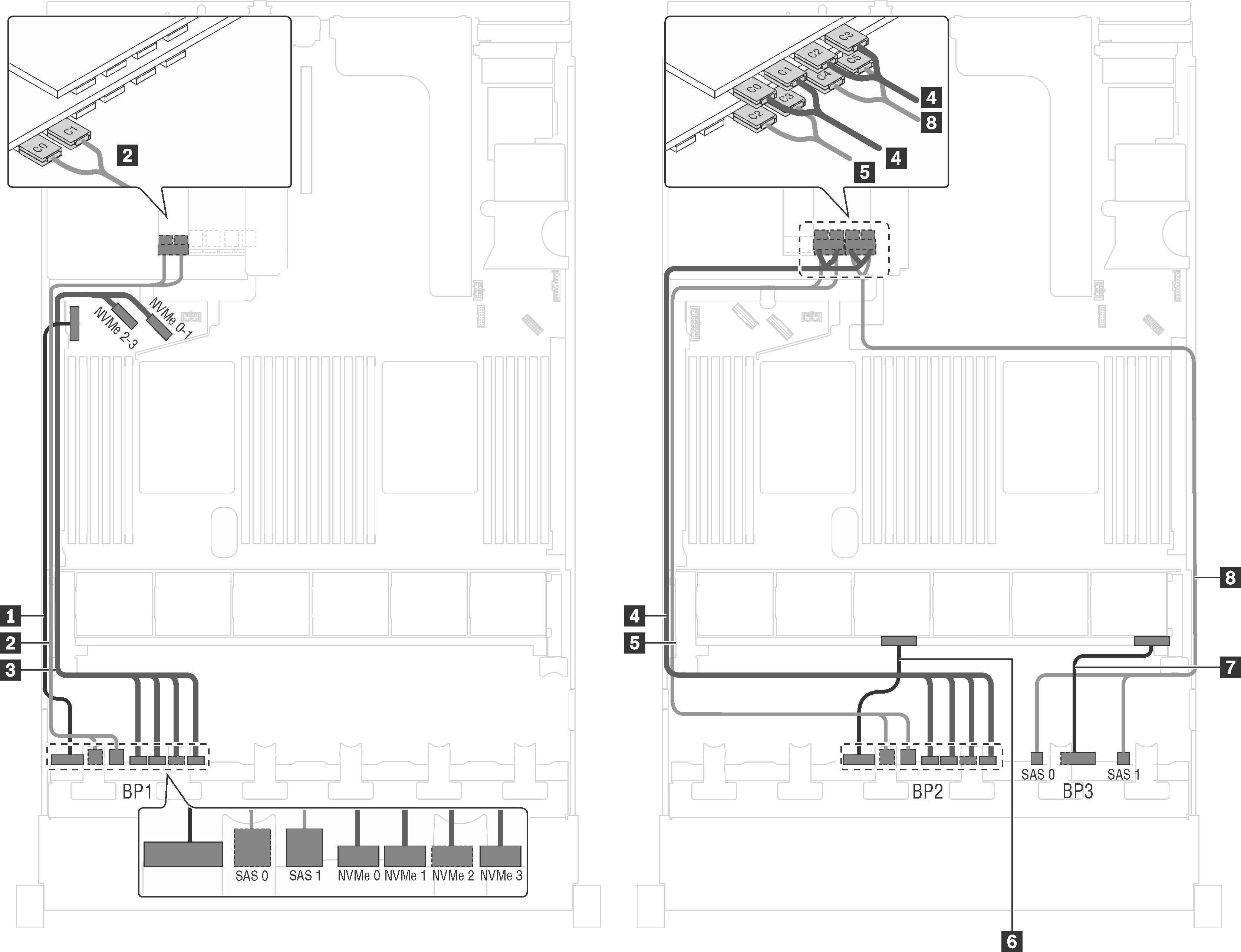
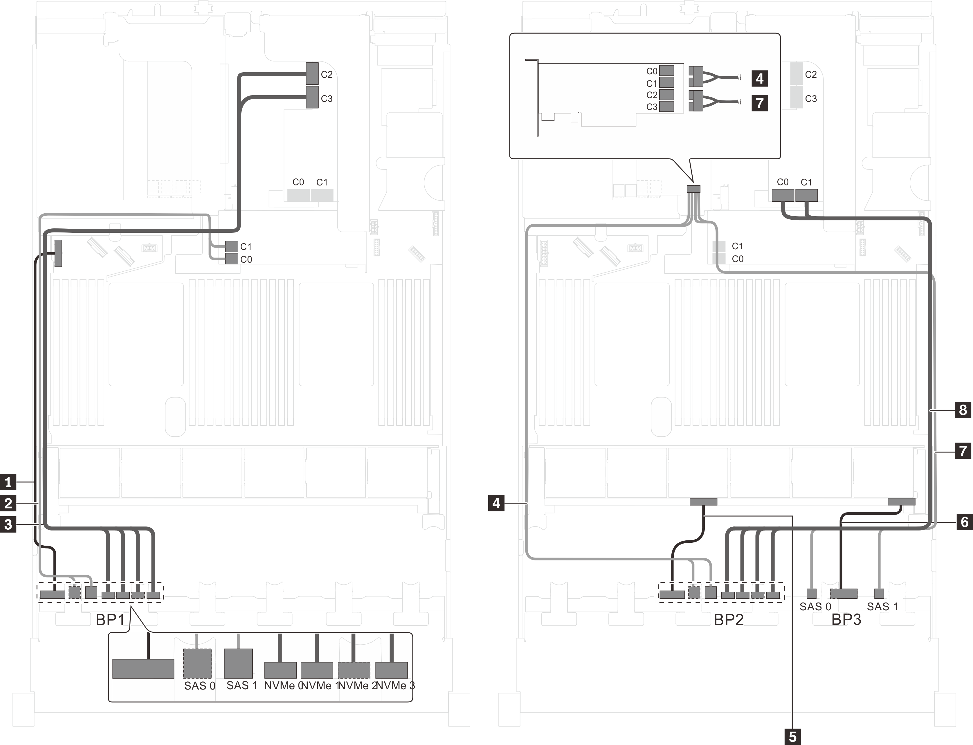
Server model: twenty-four 2.5-inch SAS/SATA drives, one 8i HBA/RAID adapter, one 16i HBA/RAID adapter
Gen 4 HBA/RAID adapter cannot be installed in the inner raid adapter slot.
*When Gen 4 HBA/RAID adapter is installed, ensure you use Gen 4 SAS signal cable (ThinkSystem SR550/SR590/SR650 2.5" SAS/SATA/AnyBay 8-Bay X40 RAID Cable Kit).
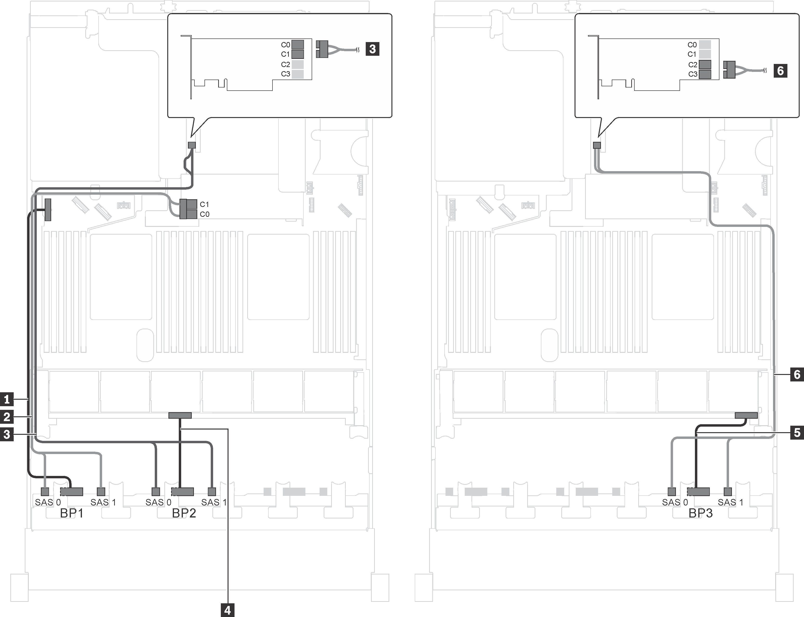
| Cable | From | To |
|---|---|---|
| 1 Power cable for front backplane 1 | Power connector on front backplane 1 | Backplane power connector 1 on the system board |
| 2 SAS signal cable for front backplane 1* | SAS 0 and SAS 1 connectors on front backplane 1 | 8i HBA/RAID adapter on the RAID adapter slot
|
| 3 SAS signal cable for front backplane 2* | SAS 0 and SAS 1 connectors on front backplane 2 | 16i HBA/RAID adapter on PCIe slot 4
|
| 4 Power cable for front backplane 2 | Power connector on front backplane 2 | Backplane power connector 2 on the system board |
| 5 Power cable for front backplane 3 | Power connector on front backplane 3 | Backplane power connector 3 on the system board |
| 6 SAS signal cable for front backplane 3* | SAS 0 and SAS 1 connectors on front backplane 3 | 16i HBA/RAID adapter on PCIe slot 4
|
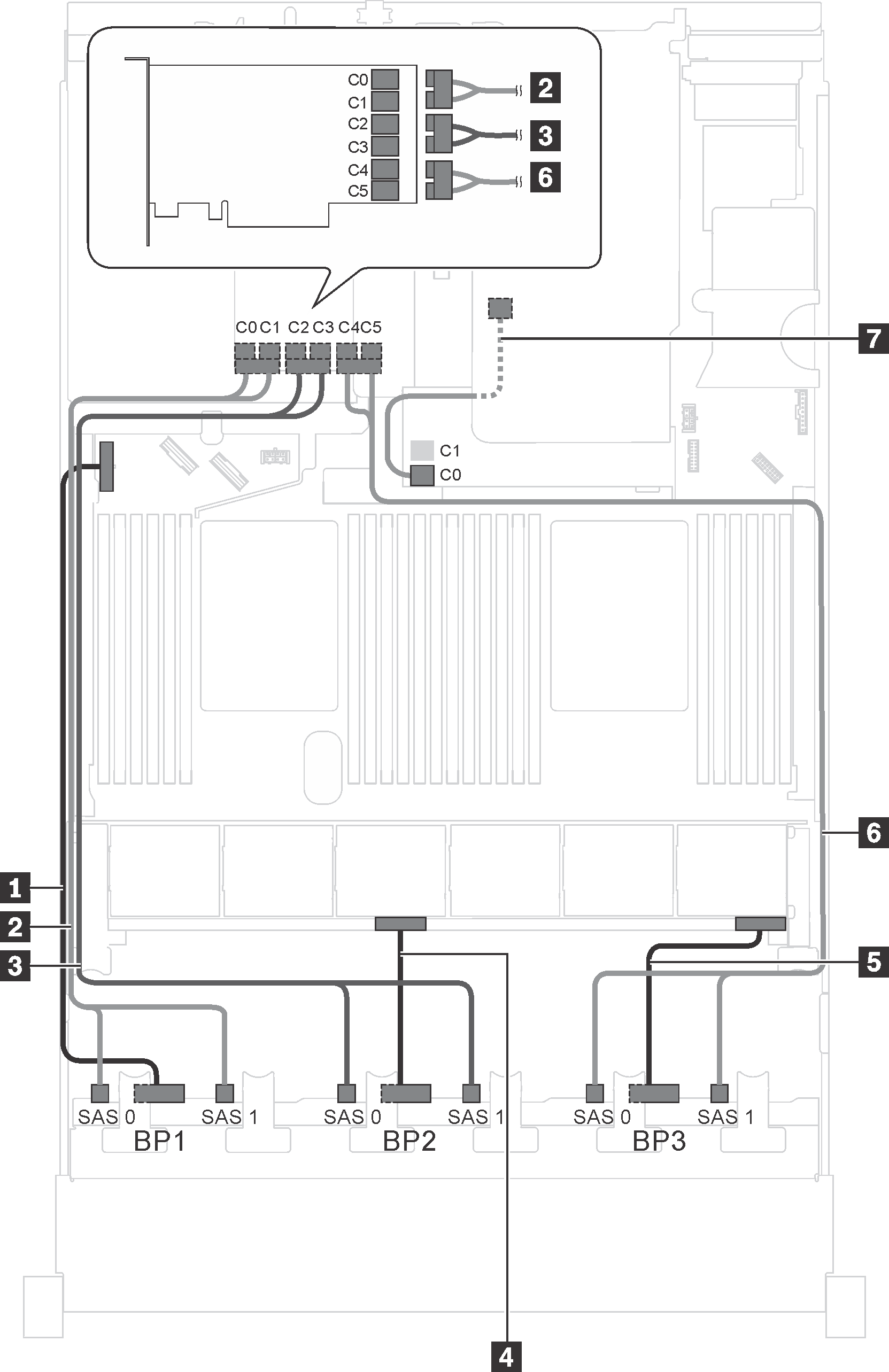
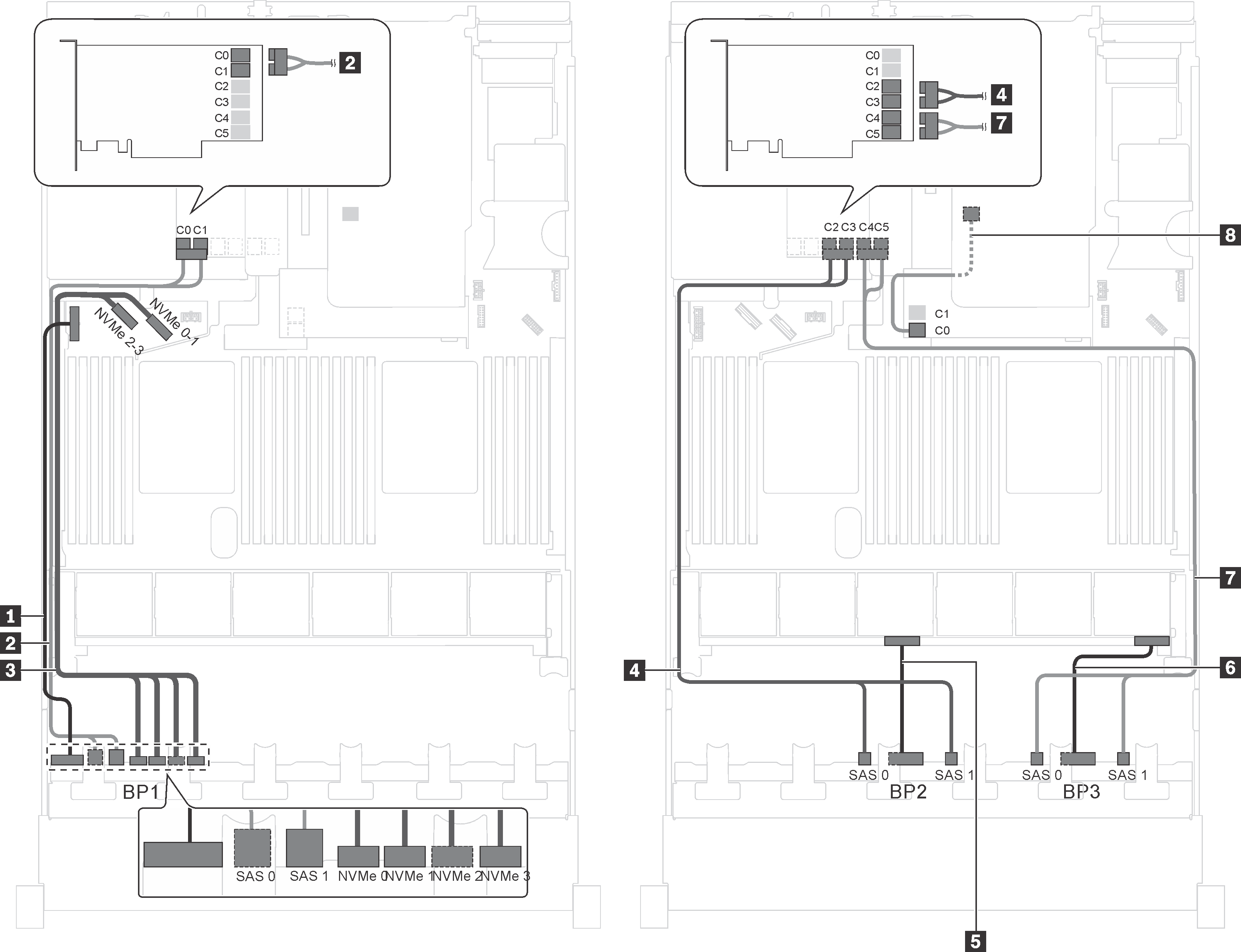
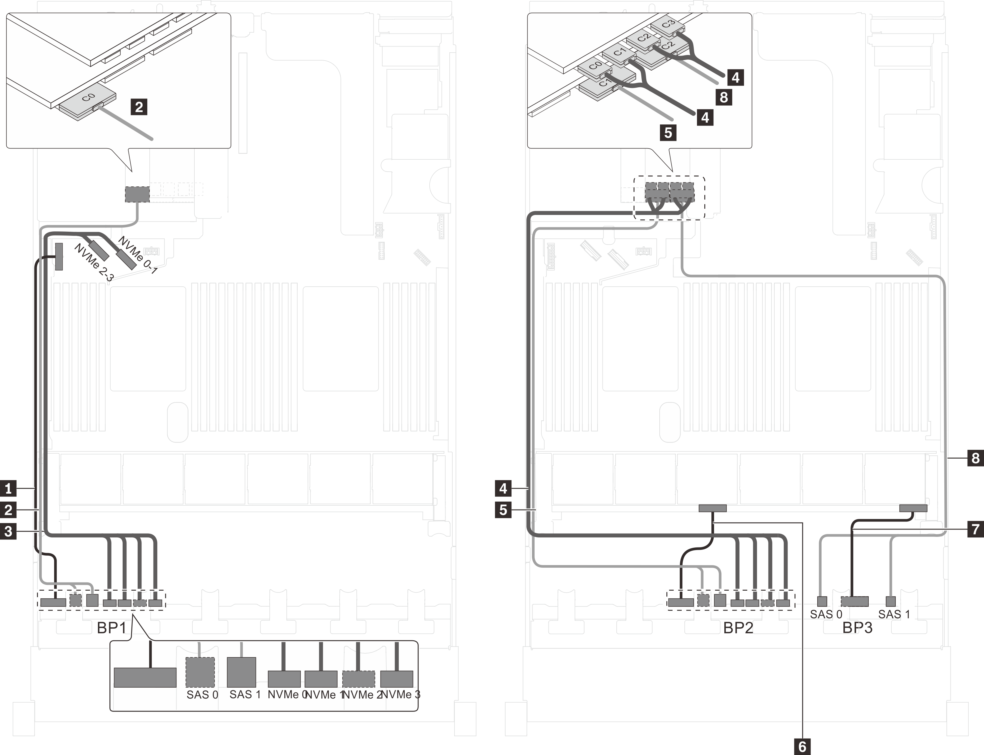
Server model: twenty-four 2.5-inch SAS/SATA drives, one 24i RAID adapter
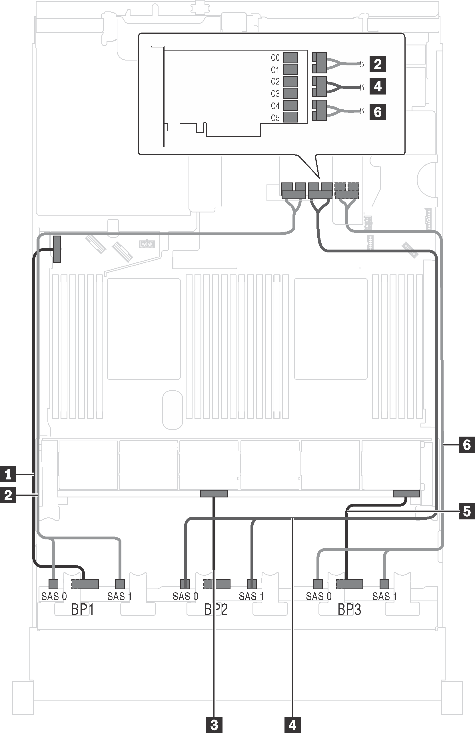
| Cable | From | To |
|---|---|---|
| 1 Power cable for front backplane 1 | Power connector on front backplane 1 | Backplane power connector 1 on the system board |
| 2 SAS signal cable for front backplane 1 | SAS 0 and SAS 1 connectors on front backplane 1 | C0 and C1 connectors on the 24i RAID adapter on riser 1 assembly |
| 3 Power cable for front backplane 2 | Power connector on front backplane 2 | Backplane power connector 2 on the system board |
| 4 SAS signal cable for front backplane 2 | SAS 0 and SAS 1 connectors on front backplane 2 | C2 and C3 connectors on the 24i RAID adapter on riser 1 assembly |
| 5 Power cable for front backplane 3 | Power connector on front backplane 3 | Backplane power connector 3 on the system board |
| 6 SAS signal cable for front backplane 3 | SAS 0 and SAS 1 connectors on front backplane 3 | C4 and C5 connectors on the 24i RAID adapter on riser 1 assembly |
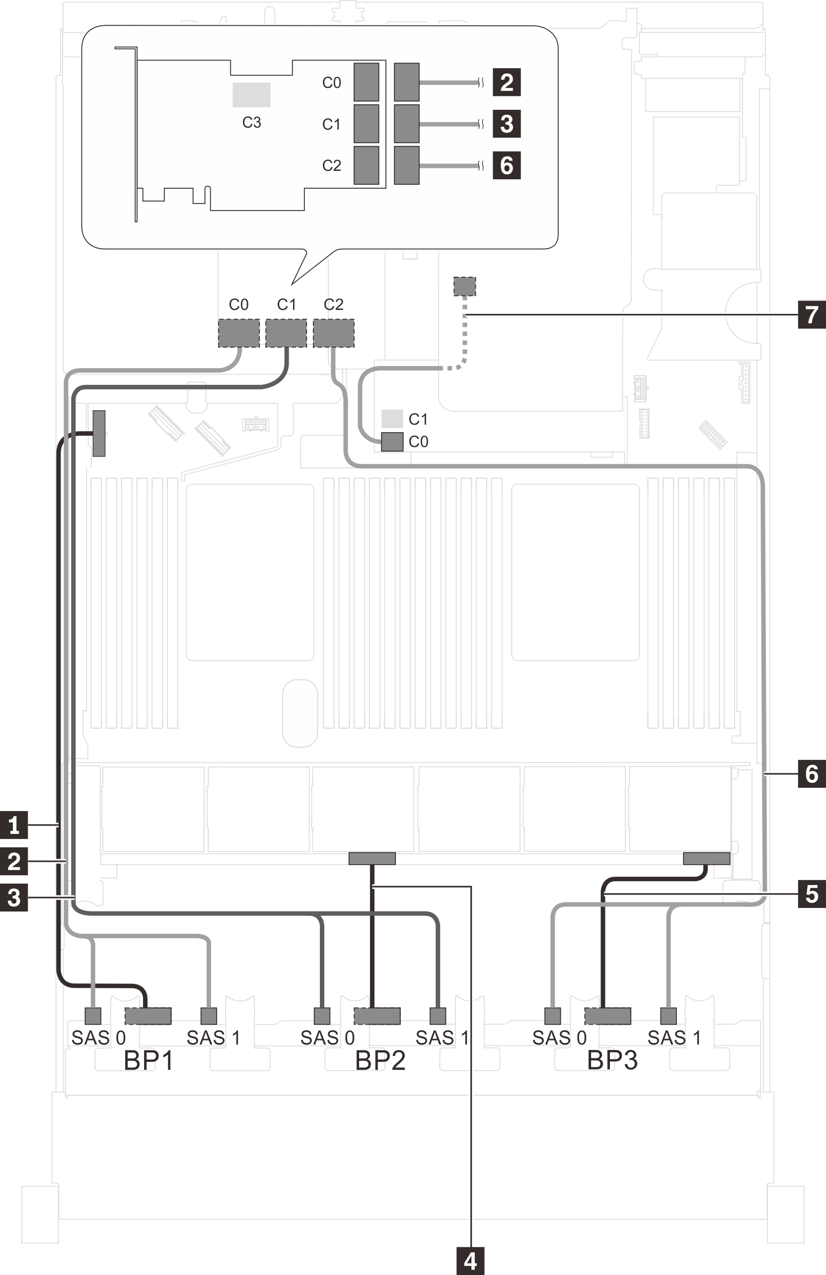
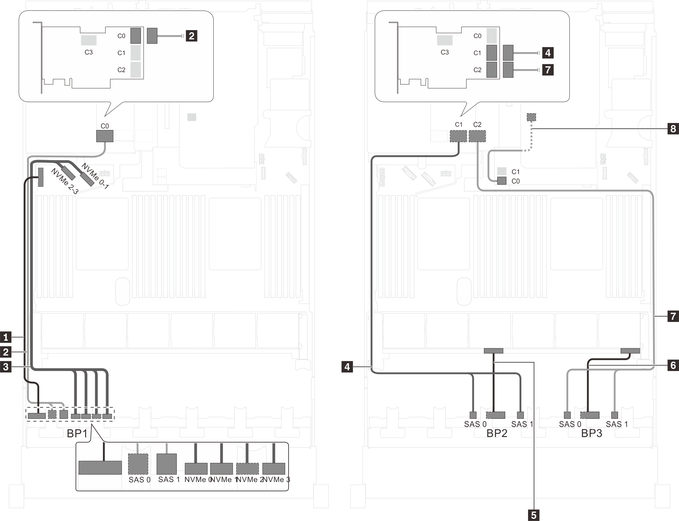
Server model: twenty-four 2.5-inch SAS/SATA drives, one 32i RAID adapter
Gen 4 HBA/RAID adapter cannot be installed in the inner raid adapter slot.
*Ensure you use Gen 4 SAS signal cable (ThinkSystem SR550/SR590/SR650 2.5" SAS/SATA/AnyBay 8-Bay X40 RAID Cable Kit).
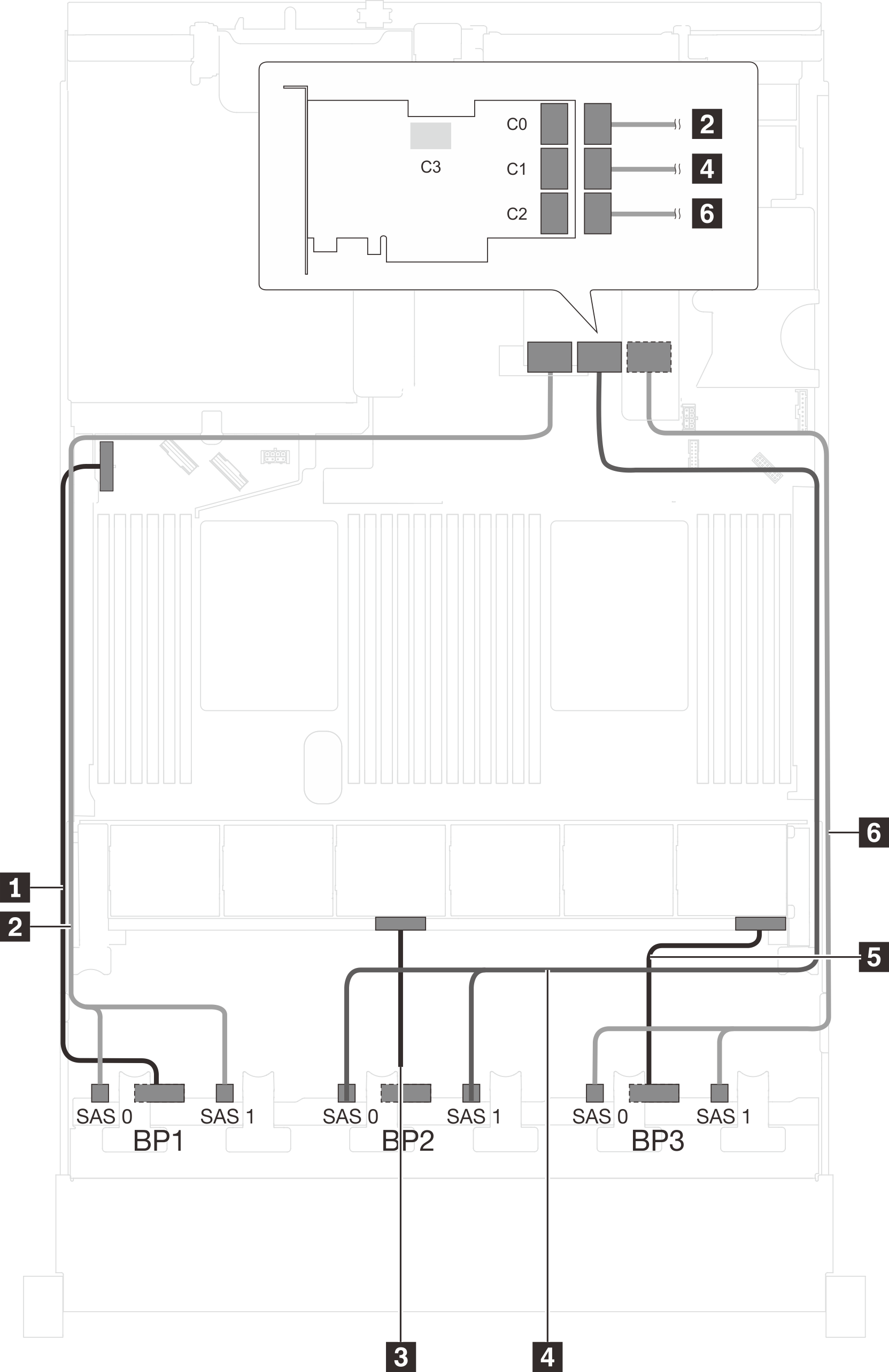
| Cable | From | To |
|---|---|---|
| 1 Power cable for front backplane 1 | Power connector on front backplane 1 | Backplane power connector 1 on the system board |
| 2 SAS signal cable for front backplane 1* | SAS 0 and SAS 1 connectors on front backplane 1 | C0 connector on the 32i RAID adapter on riser 1 assembly |
| 3 Power cable for front backplane 2 | Power connector on front backplane 2 | Backplane power connector 2 on the system board |
| 4 SAS signal cable for front backplane 2* | SAS 0 and SAS 1 connectors on front backplane 2 | C1 connectors on the 32i RAID adapter on riser 1 assembly |
| 5 Power cable for front backplane 3 | Power connector on front backplane 3 | Backplane power connector 3 on the system board |
| 6 SAS signal cable for front backplane 3* | SAS 0 and SAS 1 connectors on front backplane 3 | C2 connector on the 32i RAID adapter on riser 1 assembly |
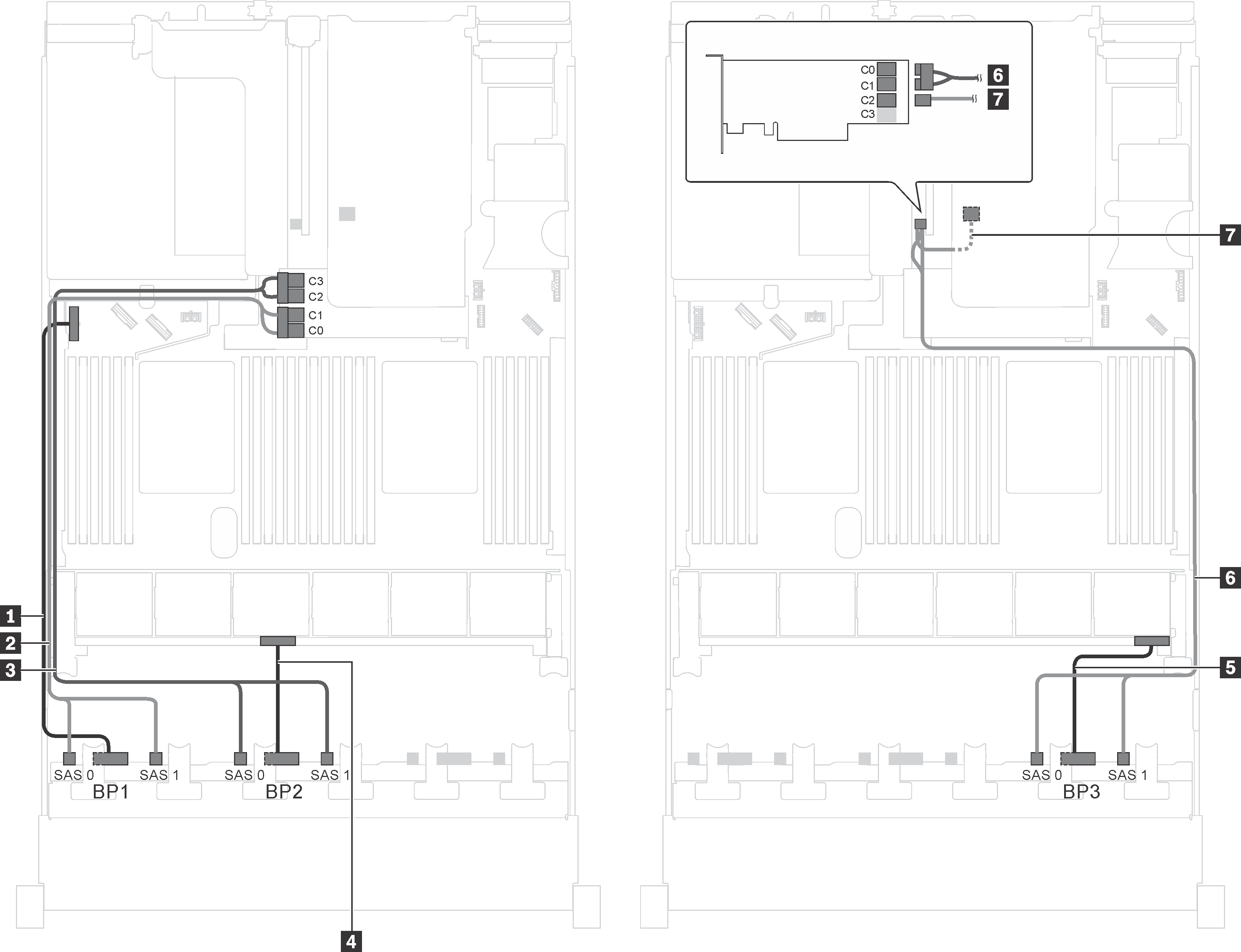
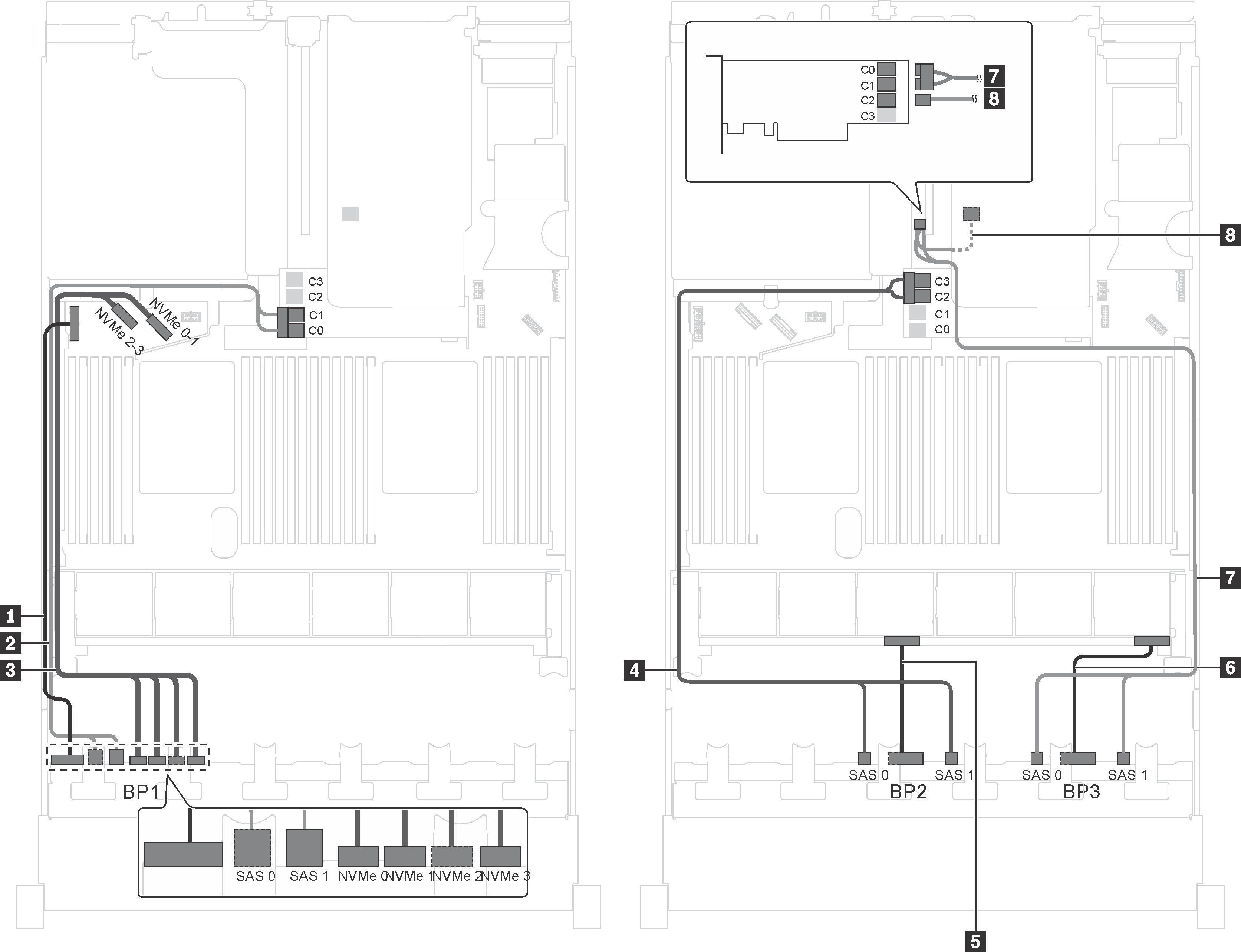
Server model: twenty-four 2.5-inch SAS/SATA drives, the rear hot-swap drive assembly, four 8i HBA/RAID adapters
The cable routing illustration is based on the scenario that the rear hot-swap drive assembly is installed. Depending on the model, the rear hot-swap drive assembly and the 8i HBA/RAID adapter in PCIe slot 6 might not be available on your server.
Gen 4 HBA/RAID adapter cannot be installed in the inner raid adapter slot.
- *When Gen 4 HBA/RAID adapter is installed, ensure you use Gen 4 SAS signal cable:
Cable 6: ThinkSystem SR550/SR590/SR650 2.5" SAS/SATA/AnyBay 8-Bay X40 RAID Cable Kit
Cable 7: ThinkSystem SR590/SR650 3.5" SAS/SATA 2-Bay Rear BP X40 RAID Cable Kit
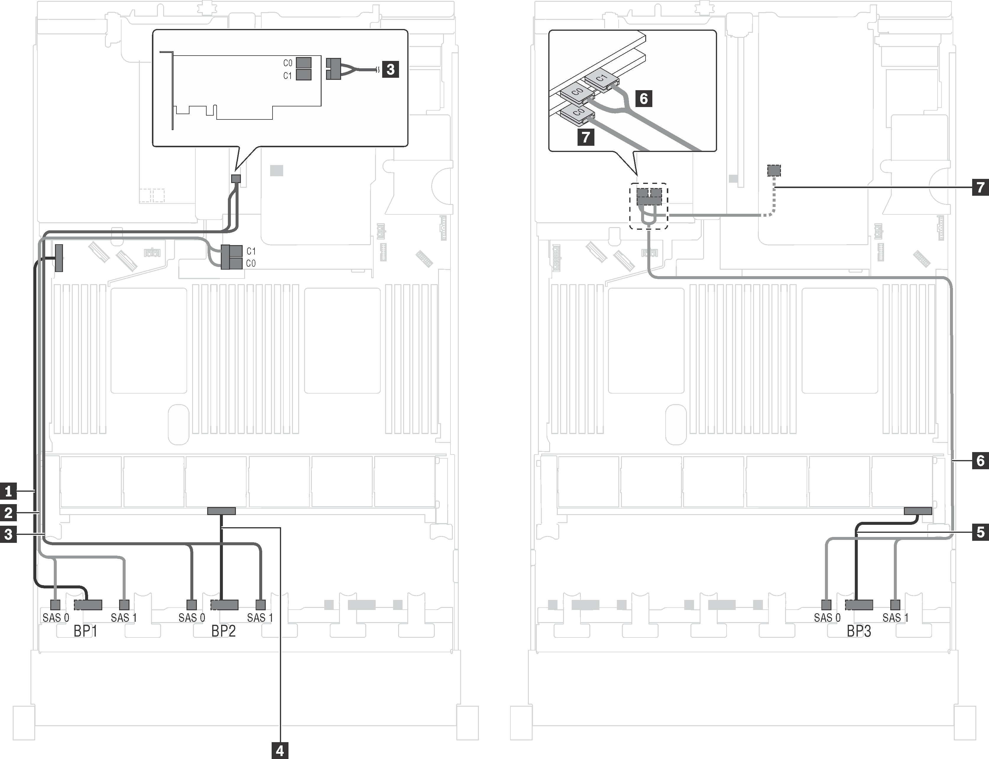
| Cable | From | To |
|---|---|---|
| 1 Power cable for front backplane 1 | Power connector on front backplane 1 | Backplane power connector 1 on the system board |
| 2 SAS signal cable for front backplane 1* | SAS 0 and SAS 1 connectors on front backplane 1 | 8i HBA/RAID adapter on the RAID adapter slot
|
| 3 SAS signal cable for front backplane 2* | SAS 0 and SAS 1 connectors on front backplane 2 | 8i HBA/RAID adapter on PCIe slot 4
|
| 4 Power cable for front backplane 2 | Power connector on front backplane 2 | Backplane power connector 2 on the system board |
| 5 Power cable for front backplane 3 | Power connector on front backplane 3 | Backplane power connector 3 on the system board |
| 6 SAS signal cable for front backplane 3* | SAS 0 and SAS 1 connectors on front backplane 3 | 8i HBA/RAID adapter on PCIe slot 5
|
| 7 SAS signal cable for the rear hot-swap drive assembly* | Signal connector on the rear hot-swap drive assembly | 8i HBA/RAID adapter installed in PCIe slot 6
|
Server model: twenty-four 2.5-inch SAS/SATA drives, the rear hot-swap drive assembly, two 8i HBA/RAID adapters, one 16i HBA/RAID adapter
Gen 4 HBA/RAID adapter cannot be installed in the inner raid adapter slot.
- *When Gen 4 HBA/RAID adapter is installed, ensure you use Gen 4 SAS signal cable:
Cable 2/3/6: ThinkSystem SR550/SR590/SR650 2.5" SAS/SATA/AnyBay 8-Bay X40 RAID Cable Kit
Cable 7: ThinkSystem SR590/SR650 3.5" SAS/SATA 2-Bay Rear BP X40 RAID Cable Kit
| Cable | From | To |
|---|---|---|
| 1 Power cable for front backplane 1 | Power connector on front backplane 1 | Backplane power connector 1 on the system board |
| 2 SAS signal cable for front backplane 1* | SAS 0 and SAS 1 connectors on front backplane 1 | 8i HBA/RAID adapter on the RAID adapter slot
|
| 3 SAS signal cable for front backplane 2* | SAS 0 and SAS 1 connectors on front backplane 2 | 8i HBA/RAID adapter on PCIe slot 4
|
| 4 Power cable for front backplane 2 | Power connector on front backplane 2 | Backplane power connector 2 on the system board |
| 5 Power cable for front backplane 3 | Power connector on front backplane 3 | Backplane power connector 3 on the system board |
| 6 SAS signal cable for front backplane 3* | SAS 0 and SAS 1 connectors on front backplane 3 | 16i HBA/RAID adapter on PCIe slot 5
|
| 7 SAS signal cable for the rear hot-swap drive assembly* | Signal connector on the rear hot-swap drive assembly | 16i HBA/RAID adapter on PCIe slot 5
|
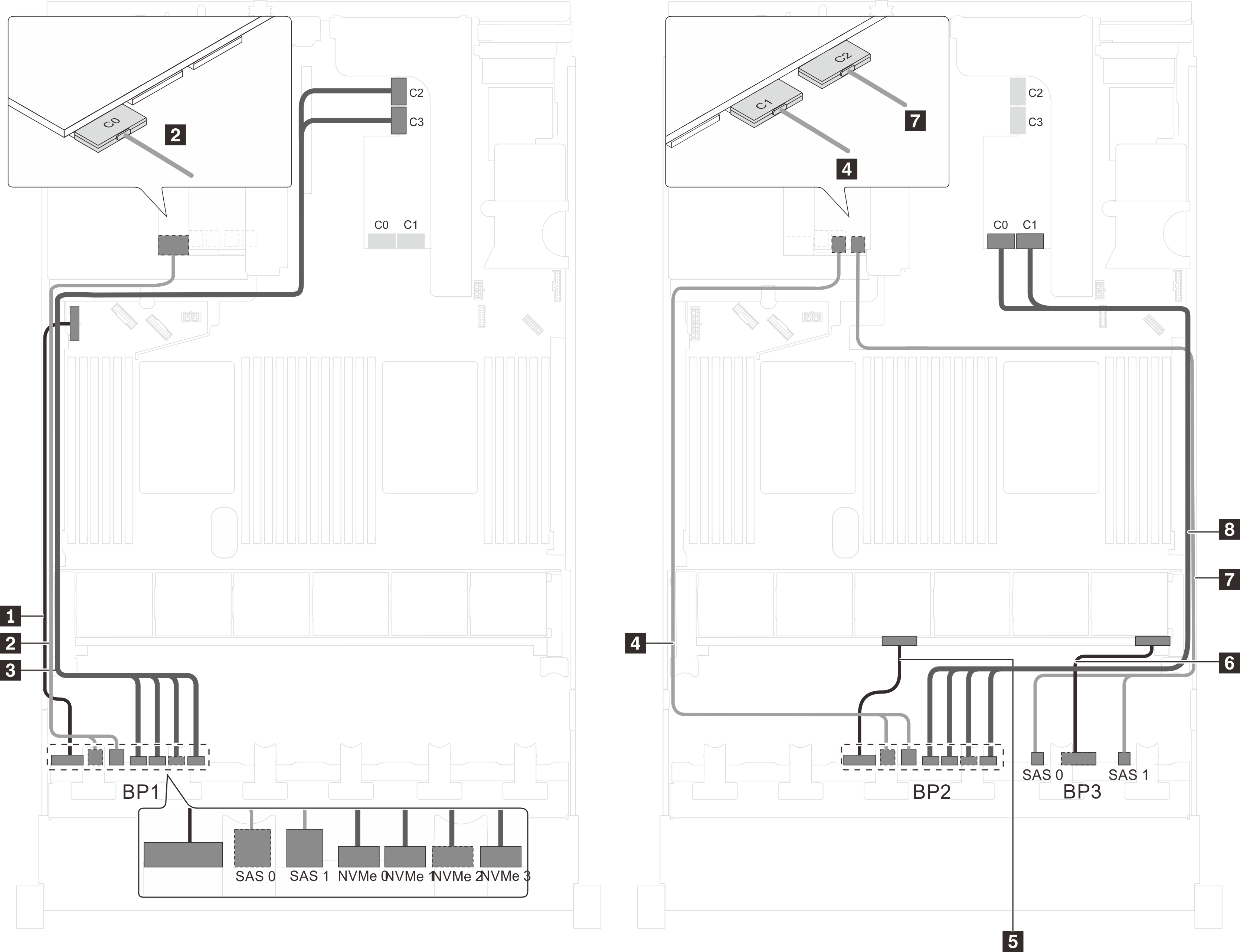
Server model: twenty-four 2.5-inch SAS/SATA drives, the rear hot-swap drive assembly, one 8i HBA/RAID adapter, one 24i RAID adapter
Gen 4 HBA/RAID adapter cannot be installed in the inner raid adapter slot.
*When Gen 4 HBA/RAID adapter is installed, ensure you use Gen 4 SAS signal cable (ThinkSystem SR590/SR650 3.5" SAS/SATA 2-Bay Rear BP X40 RAID Cable Kit).
| Cable | From | To |
|---|---|---|
| 1 Power cable for front backplane 1 | Power connector on front backplane 1 | Backplane power connector 1 on the system board |
| 2 SAS signal cable for front backplane 1 | SAS 0 and SAS 1 connectors on front backplane 1 | C0 and C1 connectors on the 24i RAID adapter installed in PCIe slot 5 |
| 3 SAS signal cable for front backplane 2 | SAS 0 and SAS 1 connectors on front backplane 2 | C2 and C3 connectors on the 24i RAID adapter installed in PCIe slot 5 |
| 4 Power cable for front backplane 2 | Power connector on front backplane 2 | Backplane power connector 2 on the system board |
| 5 Power cable for front backplane 3 | Power connector on front backplane 3 | Backplane power connector 3 on the system board |
| 6 SAS signal cable for front backplane 3 | SAS 0 and SAS 1 connectors on front backplane 3 | C4 and C5 connectors on the 24i RAID adapter installed in PCIe slot 5 |
| 7 SAS signal cable for the rear hot-swap drive assembly* | Signal connector on the rear hot-swap drive assembly | 8i HBA/RAID adapter on the RAID adapter slot
|
Server model: twenty-four 2.5-inch SAS/SATA drives, the rear hot-swap drive assembly, one 8i HBA/RAID adapter, one 32i RAID adapter
Gen 4 HBA/RAID adapter cannot be installed in the inner raid adapter slot.
- *When Gen 4 HBA/RAID adapter is installed, ensure you use Gen 4 SAS signal cable:
Cable 2/3/6: ThinkSystem SR550/SR590/SR650 2.5" SAS/SATA/AnyBay 8-Bay X40 RAID Cable Kit
Cable 7: ThinkSystem SR590/SR650 3.5" SAS/SATA 2-Bay Rear BP X40 RAID Cable Kit
| Cable | From | To |
|---|---|---|
| 1 Power cable for front backplane 1 | Power connector on front backplane 1 | Backplane power connector 1 on the system board |
| 2 SAS signal cable for front backplane 1* | SAS 0 and SAS 1 connectors on front backplane 1 | C0 connector on the 32i RAID adapter on PCIe slot 5 |
| 3 SAS signal cable for front backplane 2* | SAS 0 and SAS 1 connectors on front backplane 2 | C1 connector on the 32i RAID adapter on PCIe slot 5 |
| 4 Power cable for front backplane 2 | Power connector on front backplane 2 | Backplane power connector 2 on the system board |
| 5 Power cable for front backplane 3 | Power connector on front backplane 3 | Backplane power connector 3 on the system board |
| 6 SAS signal cable for front backplane 3* | SAS 0 and SAS 1 connectors on front backplane 3 | C2 connector on the 32i RAID adapter on PCIe slot 5 |
| 7 SAS signal cable for the rear hot-swap drive assembly* | Signal connector on the rear hot-swap drive assembly | 8i HBA/RAID adapter on the RAID adapter slot
|
Server model: twenty-four 2.5-inch SAS/SATA drives, the rear hot-swap drive assembly, two 16i HBA/RAID adapters
Gen 4 HBA/RAID adapter cannot be installed in the inner raid adapter slot.
- *When Gen 4 HBA/RAID adapter is installed, ensure you use Gen 4 SAS signal cable:
Cable 2/3/6: ThinkSystem SR550/SR590/SR650 2.5" SAS/SATA/AnyBay 8-Bay X40 RAID Cable Kit
Cable 7: ThinkSystem SR590/SR650 3.5" SAS/SATA 2-Bay Rear BP X40 RAID Cable Kit
| Cable | From | To |
|---|---|---|
| 1 Power cable for front backplane 1 | Power connector on front backplane 1 | Backplane power connector 1 on the system board |
| 2 SAS signal cable for front backplane 1* | SAS 0 and SAS 1 connectors on front backplane 1 | 16i HBA/RAID adapter on the RAID adapter slot
|
| 3 SAS signal cable for front backplane 2* | SAS 0 and SAS 1 connectors on front backplane 2 | 16i HBA/RAID adapter on the RAID adapter slot
|
| 4 Power cable for front backplane 2 | Power connector on front backplane 2 | Backplane power connector 2 on the system board |
| 5 Power cable for front backplane 3 | Power connector on front backplane 3 | Backplane power connector 3 on the system board |
| 6 SAS signal cable for front backplane 3* | SAS 0 and SAS 1 connectors on front backplane 3 | 16i HBA/RAID adapter on PCIe slot 4
|
| 7 SAS signal cable for the rear hot-swap drive assembly* | Signal connector on the rear hot-swap drive assembly | 16i HBA/RAID adapter on PCIe slot 4
|
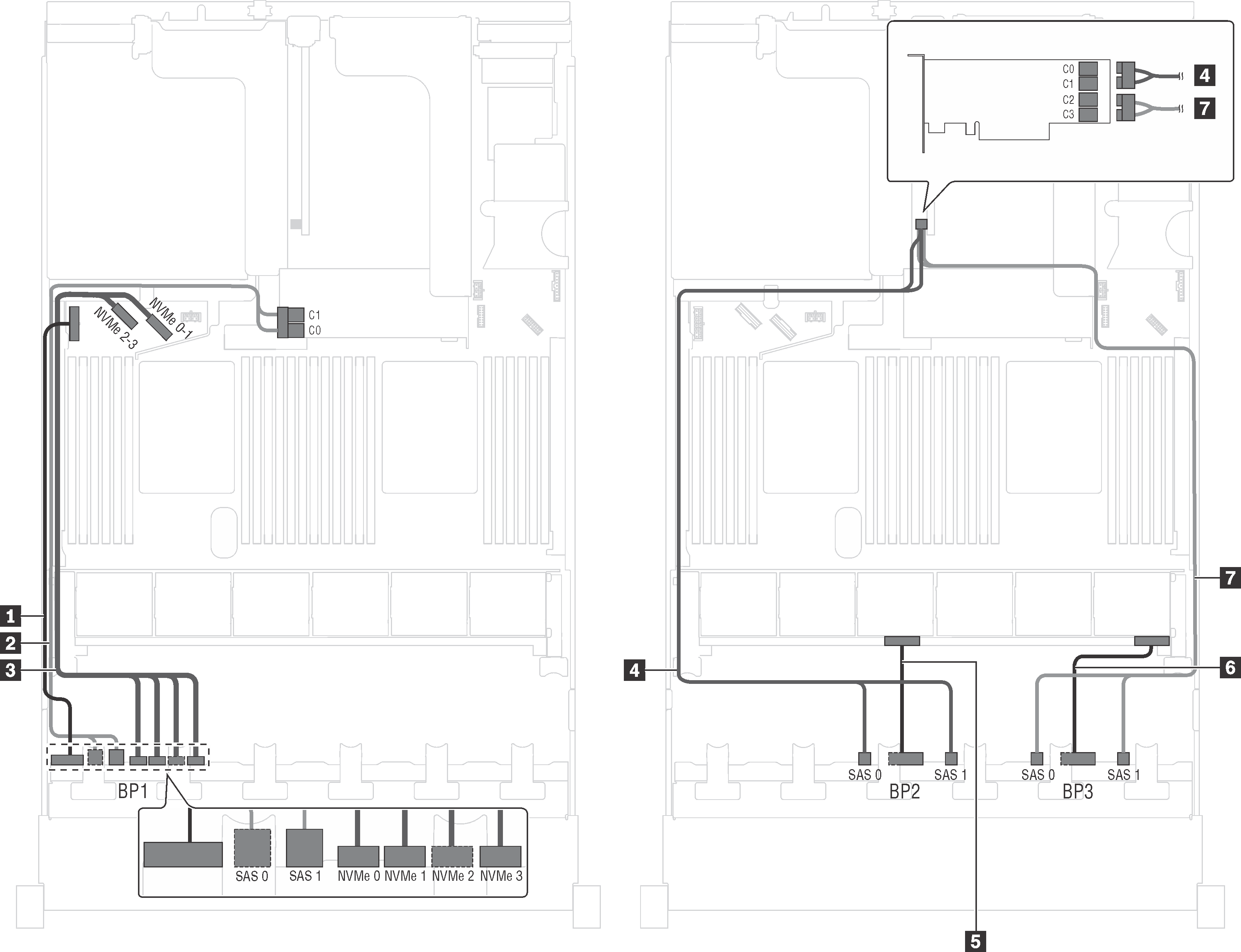
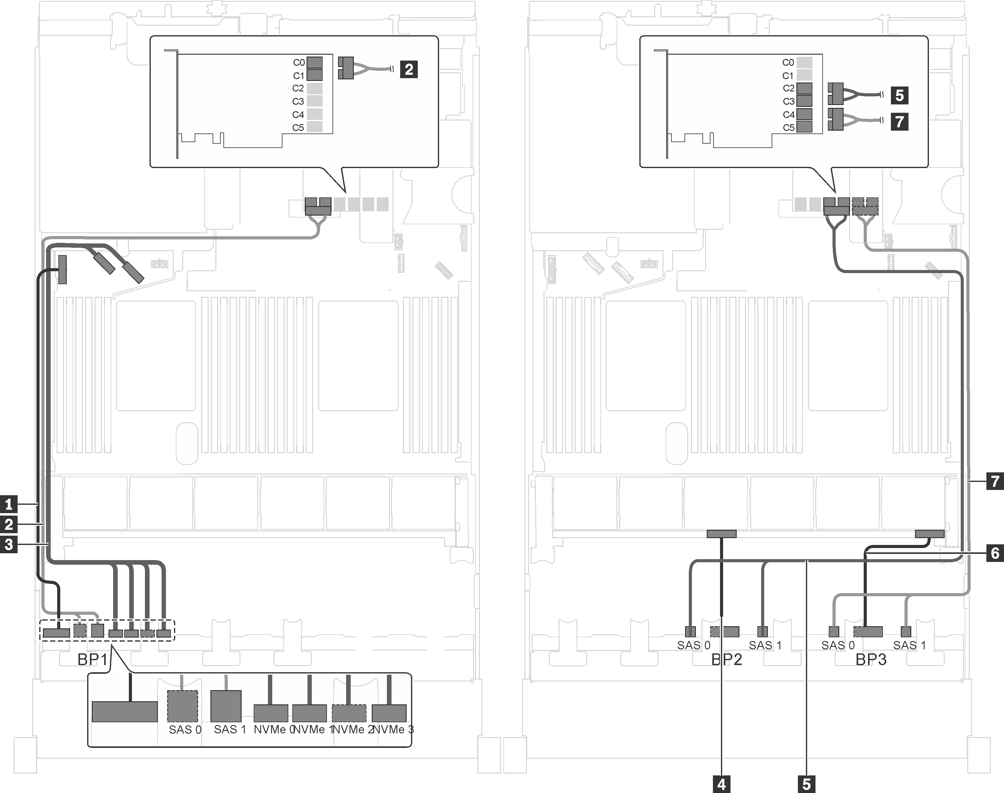
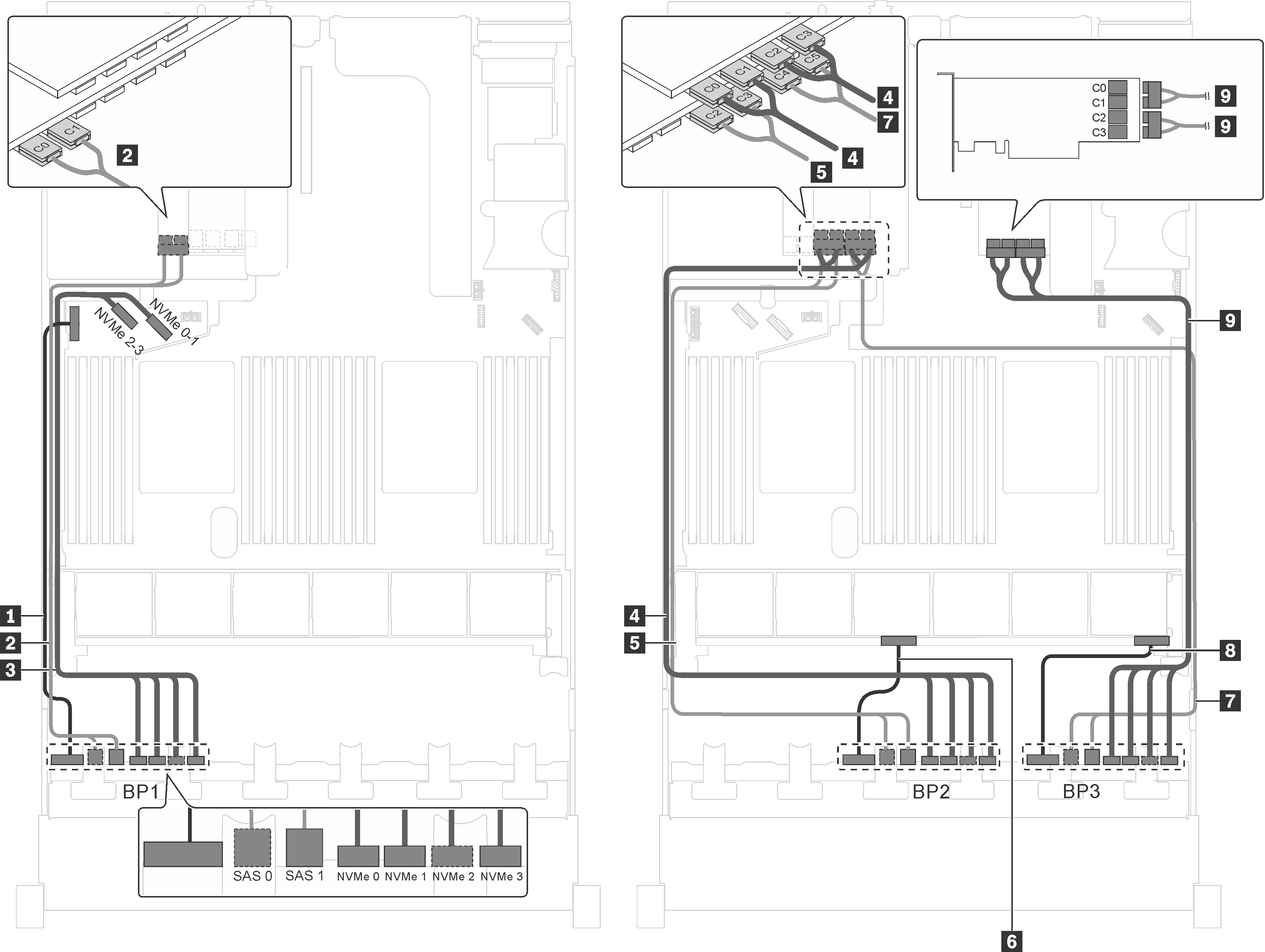
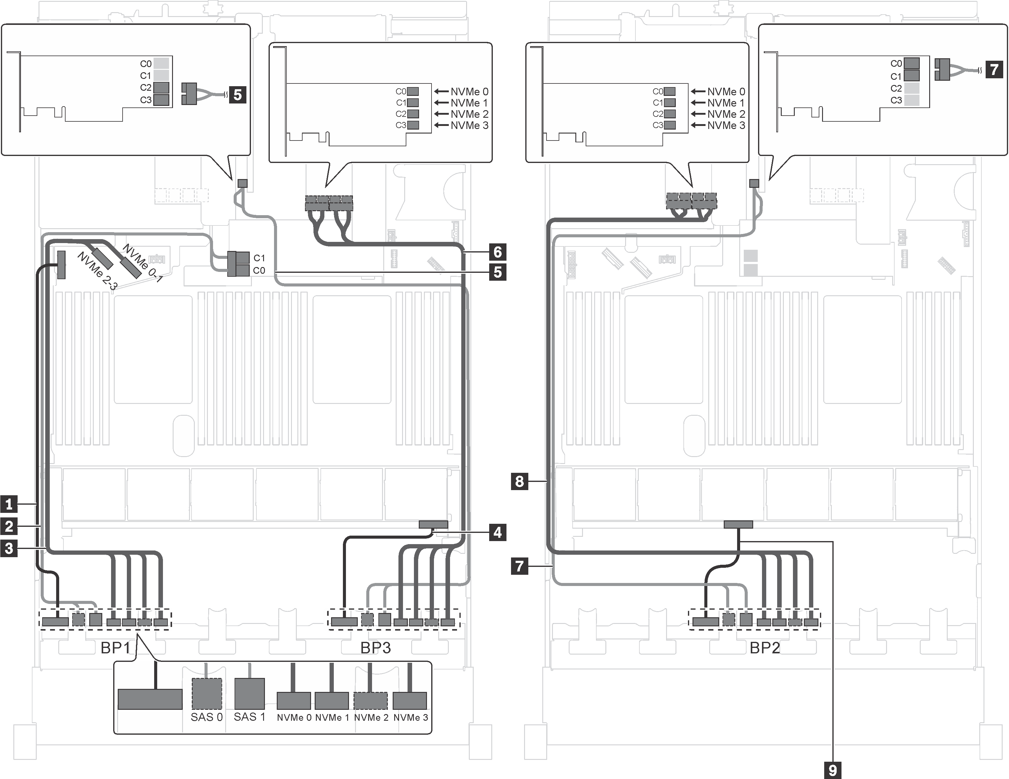
Server model: twenty 2.5-inch SAS/SATA drives, four 2.5-inch SAS/SATA/NVMe drives, one 8i HBA/RAID adapter, one 16i HBA/RAID adapter
Gen 4 HBA/RAID adapter cannot be installed in the inner raid adapter slot.
*When Gen 4 HBA/RAID adapter is installed, ensure you use Gen 4 SAS signal cable (ThinkSystem SR550/SR590/SR650 2.5" SAS/SATA/AnyBay 8-Bay X40 RAID Cable Kit).
| Cable | From | To |
|---|---|---|
| 1 Power cable for front backplane 1 | Power connector on front backplane 1 | Backplane power connector 1 on the system board |
| 2 SAS signal cable for front backplane 1* | SAS 0 and SAS 1 connectors on front backplane 1 | 16i HBA/RAID adapter on the RAID adapter slot
|
| 3 NVMe signal cable for front backplane 1 | NVMe 0, NVMe 1, NVMe 2, and NVMe 3 connectors on front backplane 1 | NVMe 0–1 and NVMe 2–3 connectors on the system board |
| 4 SAS signal cable for front backplane 2* | SAS 0 and SAS 1 connectors on front backplane 2 | 16i HBA/RAID adapter on PCIe slot 4
|
| 5 Power cable for front backplane 2 | Power connector on front backplane 2 | Backplane power connector 2 on the system board |
| 6 Power cable for front backplane 3 | Power connector on front backplane 3 | Backplane power connector 3 on the system board |
| 7 SAS signal cable for front backplane 3* | SAS 0 and SAS 1 connectors on front backplane 3 | 16i HBA/RAID adapter on PCIe slot 4
|
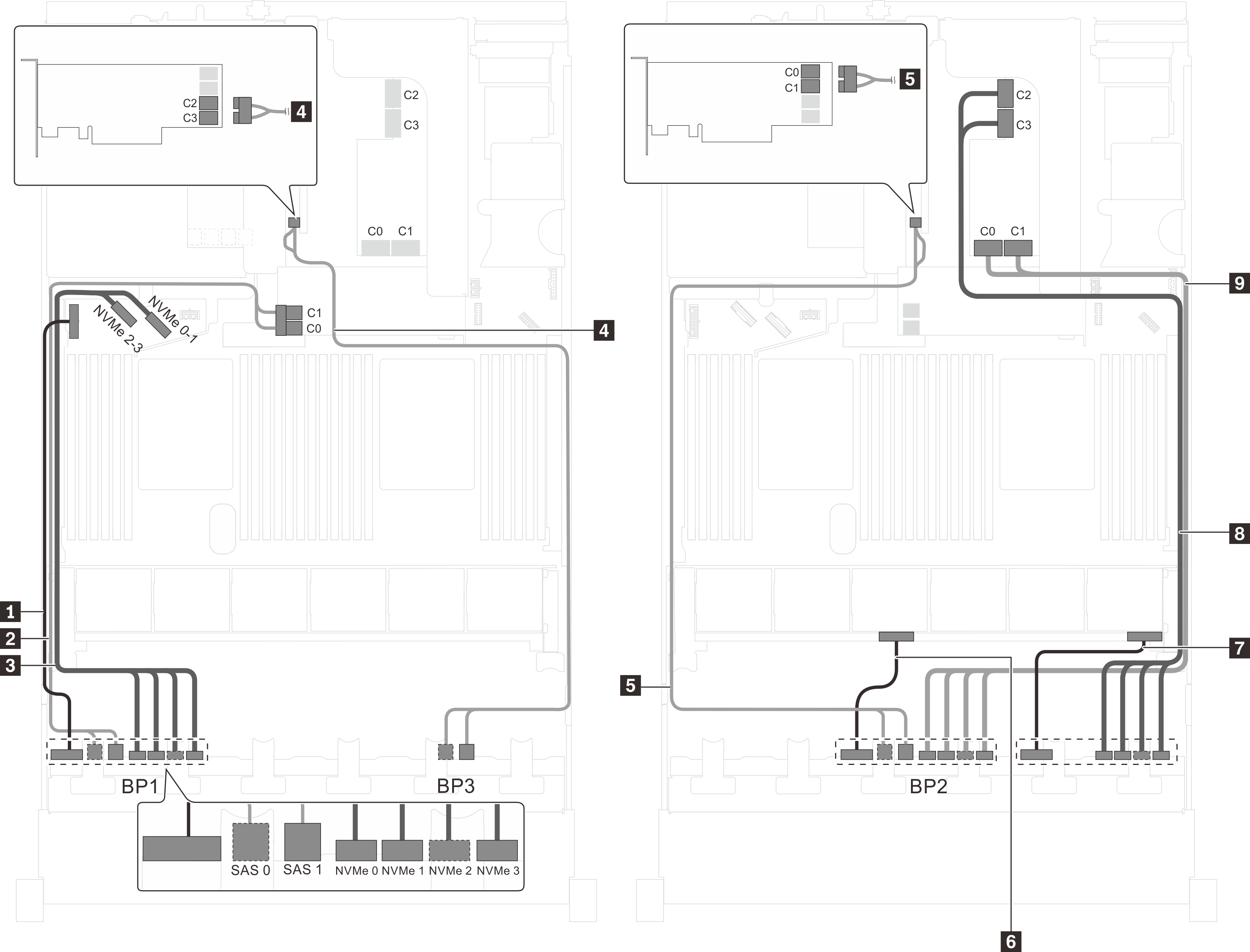
Server model: twenty 2.5-inch SAS/SATA drives, four 2.5-inch SAS/SATA/NVMe drives, one 24i RAID adapter
| Cable | From | To |
|---|---|---|
| 1 Power cable for front backplane 1 | Power connector on front backplane 1 | Backplane power connector 1 on the system board |
| 2 SAS signal cable for front backplane 1 | SAS 0 and SAS 1 connectors on front backplane 1 | C0 and C1 connectors on the 24i RAID adapter on riser 1 assembly |
| 3 NVMe signal cable for front backplane 1 | NVMe 0, NVMe 1, NVMe 2, and NVMe 3 connectors on front backplane 1 | NVMe 0–1 and NVMe 2–3 connectors on the system board |
| 4 Power cable for front backplane 2 | Power connector on front backplane 2 | Backplane power connector 2 on the system board |
| 5 SAS signal cable for front backplane 2 | SAS 0 and SAS 1 connectors on front backplane 2 | C2 and C3 connectors on the 24i RAID adapter on riser 1 assembly |
| 6 Power cable for front backplane 3 | Power connector on front backplane 3 | Backplane power connector 3 on the system board |
| 7 SAS signal cable for front backplane 3 | SAS 0 and SAS 1 connectors on front backplane 3 | C4 and C5 connectors on the 24i RAID adapter on riser 1 assembly |
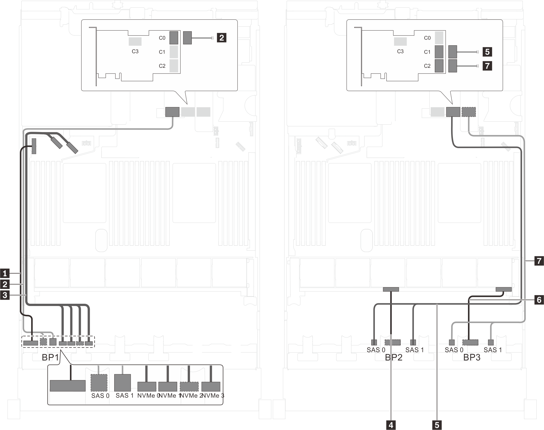
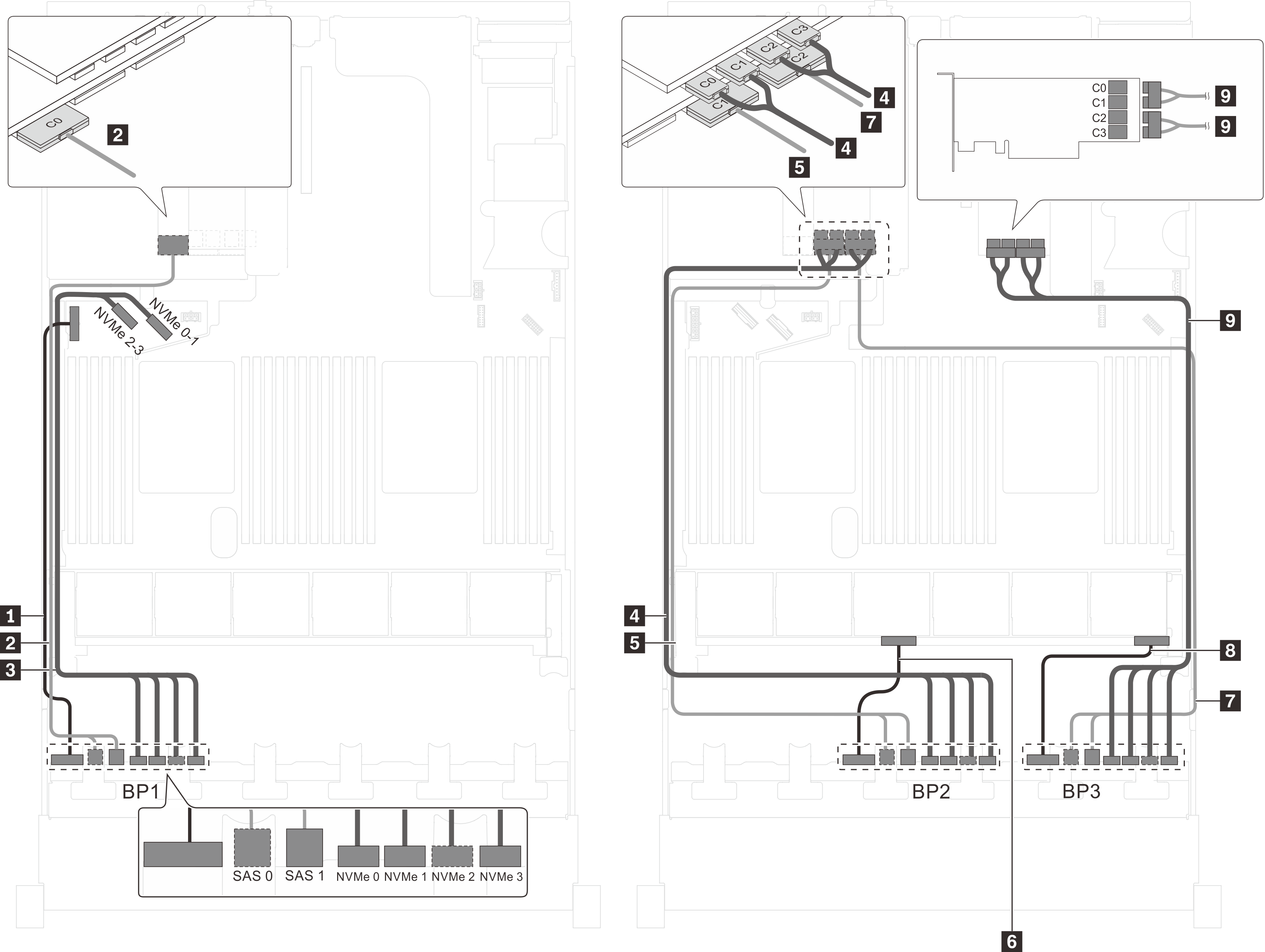
Server model: twenty 2.5-inch SAS/SATA drives, four 2.5-inch SAS/SATA/NVMe drives, one 32i RAID adapter
Gen 4 HBA/RAID adapter cannot be installed in the inner raid adapter slot.
*Ensure you use Gen 4 SAS signal cable (ThinkSystem SR550/SR590/SR650 2.5" SAS/SATA/AnyBay 8-Bay X40 RAID Cable Kit).
| Cable | From | To |
|---|---|---|
| 1 Power cable for front backplane 1 | Power connector on front backplane 1 | Backplane power connector 1 on the system board |
| 2 SAS signal cable for front backplane 1* | SAS 0 and SAS 1 connectors on front backplane 1 | C0 connector on the 32i RAID adapter on riser 1 assembly |
| 3 NVMe signal cable for front backplane 1 | NVMe 0, NVMe 1, NVMe 2, and NVMe 3 connectors on front backplane 1 | NVMe 0–1 and NVMe 2–3 connectors on the system board |
| 4 Power cable for front backplane 2 | Power connector on front backplane 2 | Backplane power connector 2 on the system board |
| 5 SAS signal cable for front backplane 2* | SAS 0 and SAS 1 connectors on front backplane 2 | C1 connector on the 32i RAID adapter on riser 1 assembly |
| 6 Power cable for front backplane 3 | Power connector on front backplane 3 | Backplane power connector 3 on the system board |
| 7 SAS signal cable for front backplane 3* | SAS 0 and SAS 1 connectors on front backplane 3 | C2 connector on the 32i RAID adapter on riser 1 assembly |
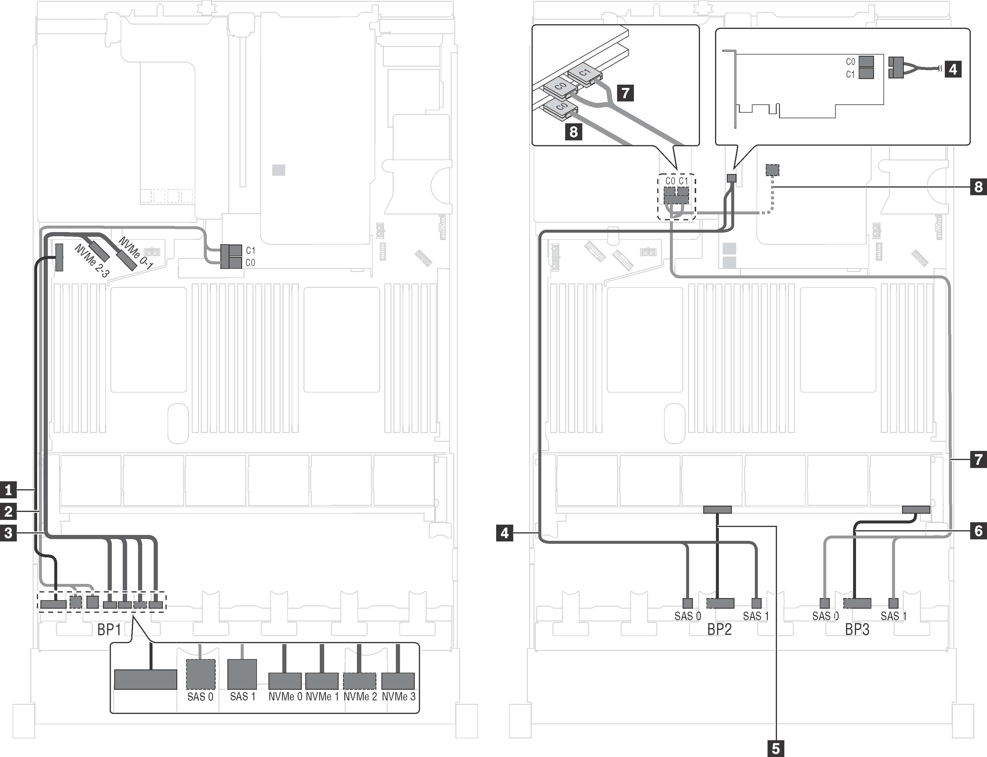
Server model: twenty 2.5-inch SAS/SATA drives, four 2.5-inch SAS/SATA/NVMe drives, the rear hot-swap drive assembly, four 8i HBA/RAID adapters
The cable routing illustration is based on the scenario that the rear hot-swap drive assembly is installed. Depending on the model, the rear hot-swap drive assembly and the 8i HBA/RAID adapter in PCIe slot 6 might not be available on your server.
Gen 4 HBA/RAID adapter cannot be installed in the inner raid adapter slot.
- *When Gen 4 HBA/RAID adapter is installed, ensure you use Gen 4 SAS signal cable (ThinkSystem SR550/SR590/SR650 2.5" SAS/SATA/AnyBay 8-Bay X40 RAID Cable Kit).
Cable 2 / Cable 4 / Cable 7: ThinkSystem SR550/SR590/SR650 2.5" SAS/SATA/AnyBay 8-Bay X40 RAID Cable Kit
Cable 8: ThinkSystem SR590/SR650 3.5" SAS/SATA 2-Bay Rear BP X40 RAID Cable Kit
| Cable | From | To |
|---|---|---|
| 1 Power cable for front backplane 1 | Power connector on front backplane 1 | Backplane power connector 1 on the system board |
| 2 SAS signal cable for front backplane 1* | SAS 0 and SAS 1 connectors on front backplane 1 | 8i HBA/RAID adapter on the RAID adapter slot
|
| 3 NVMe signal cable for front backplane 1 | NVMe 0, NVMe 1, NVMe 2, and NVMe 3 connectors on front backplane 1 | NVMe 0–1 and NVMe 2–3 connectors on the system board |
| 4 SAS signal cable for front backplane 2* | SAS 0 and SAS 1 connectors on front backplane 2 | 8i HBA/RAID adapter on PCIe slot 4
|
| 5 Power cable for front backplane 2 | Power connector on front backplane 2 | Backplane power connector 2 on the system board |
| 6 Power cable for front backplane 3 | Power connector on front backplane 3 | Backplane power connector 3 on the system board |
| 7 SAS signal cable for front backplane 3* | SAS 0 and SAS 1 connectors on front backplane 3 | 8i HBA/RAID adapter on PCIe slot 5
|
| 8 SAS signal cable for the rear hot-swap drive assembly* | Signal connector on the rear hot-swap drive assembly | 8i HBA/RAID adapter installed in PCIe slot 6
|
Server model: twenty 2.5-inch SAS/SATA drives, four 2.5-inch SAS/SATA/NVMe drives, the rear hot-swap drive assembly, two 8i HBA/RAID adapters, one 16i HBA/RAID adapter
Gen 4 HBA/RAID adapter cannot be installed in the inner raid adapter slot.
- *When Gen 4 HBA/RAID adapter is installed, ensure you use Gen 4 SAS signal cable:
Cable 2/4/7: ThinkSystem SR550/SR590/SR650 2.5" SAS/SATA/AnyBay 8-Bay X40 RAID Cable Kit
Cable 8: ThinkSystem SR590/SR650 3.5" SAS/SATA 2-Bay Rear BP X40 RAID Cable Kit
| Cable | From | To |
|---|---|---|
| 1 Power cable for front backplane 1 | Power connector on front backplane 1 | Backplane power connector 1 on the system board |
| 2 SAS signal cable for front backplane 1* | SAS 0 and SAS 1 connectors on front backplane 1 | 8i HBA/RAID adapter on the RAID adapter slot
|
| 3 NVMe signal cable for front backplane 1 | NVMe 0, NVMe 1, NVMe 2, and NVMe 3 connectors on front backplane 1 | NVMe 0–1 and NVMe 2–3 connectors on the system board |
| 4 SAS signal cable for front backplane 2* | SAS 0 and SAS 1 connectors on front backplane 2 | 8i HBA/RAID adapter on PCIe slot 4
|
| 5 Power cable for front backplane 2 | Power connector on front backplane 2 | Backplane power connector 2 on the system board |
| 6 Power cable for front backplane 3 | Power connector on front backplane 3 | Backplane power connector 3 on the system board |
| 7 SAS signal cable for front backplane 3* | SAS 0 and SAS 1 connectors on front backplane 3 | 16i HBA/RAID adapter on PCIe slot 5
|
| 8 SAS signal cable for the rear hot-swap drive assembly* | Signal connector on the rear hot-swap drive assembly | 16i HBA/RAID adapter on PCIe slot 5
|
Server model: twenty 2.5-inch SAS/SATA drives, four 2.5-inch SAS/SATA/NVMe drives, the rear hot-swap drive assembly, one 8i HBA/RAID adapter, one 24i RAID adapter
Gen 4 HBA/RAID adapter cannot be installed in the inner raid adapter slot.
*When Gen 4 HBA/RAID adapter is installed, ensure you use Gen 4 SAS signal cable (ThinkSystem SR590/SR650 3.5" SAS/SATA 2-Bay Rear BP X40 RAID Cable Kit).
| Cable | From | To |
|---|---|---|
| 1 Power cable for front backplane 1 | Power connector on front backplane 1 | Backplane power connector 1 on the system board |
| 2 SAS signal cable for front backplane 1 | SAS 0 and SAS 1 connectors on front backplane 1 | C0 and C1 connectors on the 24i RAID adapter installed in PCIe slot 5 |
| 3 NVMe signal cable for front backplane 1 | NVMe 0, NVMe 1, NVMe 2, and NVMe 3 connectors on front backplane 1 | NVMe 0–1 and NVMe 2–3 connectors on the system board |
| 4 SAS signal cable for front backplane 2 | SAS 0 and SAS 1 connectors on front backplane 2 | C2 and C3 connectors on the 24i RAID adapter installed in PCIe slot 5 |
| 5 Power cable for front backplane 2 | Power connector on front backplane 2 | Backplane power connector 2 on the system board |
| 6 Power cable for front backplane 3 | Power connector on front backplane 3 | Backplane power connector 3 on the system board |
| 7 SAS signal cable for front backplane 3 | SAS 0 and SAS 1 connectors on front backplane 3 | C4 and C5 connectors on the 24i RAID adapter installed in PCIe slot 5 |
| 8 SAS signal cable for the rear hot-swap drive assembly* | Signal connector on the rear hot-swap drive assembly | 8i HBA/RAID adapter on the RAID adapter slot
|
Server model: twenty 2.5-inch SAS/SATA drives, four 2.5-inch SAS/SATA/NVMe drives, the rear hot-swap drive assembly, one 8i HBA/RAID adapter, one 32i RAID adapter
Gen 4 HBA/RAID adapter cannot be installed in the inner raid adapter slot.
- *When Gen 4 HBA/RAID adapter is installed, ensure you use Gen 4 SAS signal cable:
Cable 2/4/7: ThinkSystem SR550/SR590/SR650 2.5" SAS/SATA/AnyBay 8-Bay X40 RAID Cable Kit
Cable 8: ThinkSystem SR590/SR650 3.5" SAS/SATA 2-Bay Rear BP X40 RAID Cable Kit
| Cable | From | To |
|---|---|---|
| 1 Power cable for front backplane 1 | Power connector on front backplane 1 | Backplane power connector 1 on the system board |
| 2 SAS signal cable for front backplane 1* | SAS 0 and SAS 1 connectors on front backplane 1 | C0 connector on the 32i RAID adapter on PCIe slot 5 |
| 3 NVMe signal cable for front backplane 1 | NVMe 0, NVMe 1, NVMe 2, and NVMe 3 connectors on front backplane 1 | NVMe 0–1 and NVMe 2–3 connectors on the system board |
| 4 SAS signal cable for front backplane 2* | SAS 0 and SAS 1 connectors on front backplane 2 | C1 connectors on the 32i RAID adapter on PCIe slot 5 |
| 5 Power cable for front backplane 2 | Power connector on front backplane 2 | Backplane power connector 2 on the system board |
| 6 Power cable for front backplane 3 | Power connector on front backplane 3 | Backplane power connector 3 on the system board |
| 7 SAS signal cable for front backplane 3* | SAS 0 and SAS 1 connectors on front backplane 3 | C2 connectors on the 32i RAID adapter on PCIe slot 5 |
| 8 SAS signal cable for the rear hot-swap drive assembly* | Signal connector on the rear hot-swap drive assembly | 8i HBA/RAID adapter on the RAID adapter slot
|
Server model: twenty 2.5-inch SAS/SATA drives, four 2.5-inch SAS/SATA/NVMe drives, the rear hot-swap drive assembly, two 16i HBA/RAID adapters
Gen 4 HBA/RAID adapter cannot be installed in the inner raid adapter slot.
- *When Gen 4 HBA/RAID adapter is installed, ensure you use Gen 4 SAS signal cable:
Cable 2/4/7: ThinkSystem SR550/SR590/SR650 2.5" SAS/SATA/AnyBay 8-Bay X40 RAID Cable Kit
Cable 8: ThinkSystem SR590/SR650 3.5" SAS/SATA 2-Bay Rear BP X40 RAID Cable Kit
| Cable | From | To |
|---|---|---|
| 1 Power cable for front backplane 1 | Power connector on front backplane 1 | Backplane power connector 1 on the system board |
| 2 SAS signal cable for front backplane 1* | SAS 0 and SAS 1 connectors on front backplane 1 | 16i HBA/RAID adapter on the RAID adapter slot
|
| 3 NVMe signal cable for front backplane 1 | NVMe 0, NVMe 1, NVMe 2, and NVMe 3 connectors on front backplane 1 | NVMe 0–1 and NVMe 2–3 connectors on the system board |
| 4 SAS signal cable for front backplane 2* | SAS 0 and SAS 1 connectors on front backplane 2 | 16i HBA/RAID adapter on the RAID adapter slot
|
| 5 Power cable for front backplane 2 | Power connector on front backplane 2 | Backplane power connector 2 on the system board |
| 6 Power cable for front backplane 3 | Power connector on front backplane 3 | Backplane power connector 3 on the system board |
| 7 SAS signal cable for front backplane 3* | SAS 0 and SAS 1 connectors on front backplane 3 | 16i HBA/RAID adapter on PCIe slot 4
|
| 8 SAS signal cable for the rear hot-swap drive assembly* | Signal connector on the rear hot-swap drive assembly | 16i HBA/RAID adapter on PCIe slot 4
|
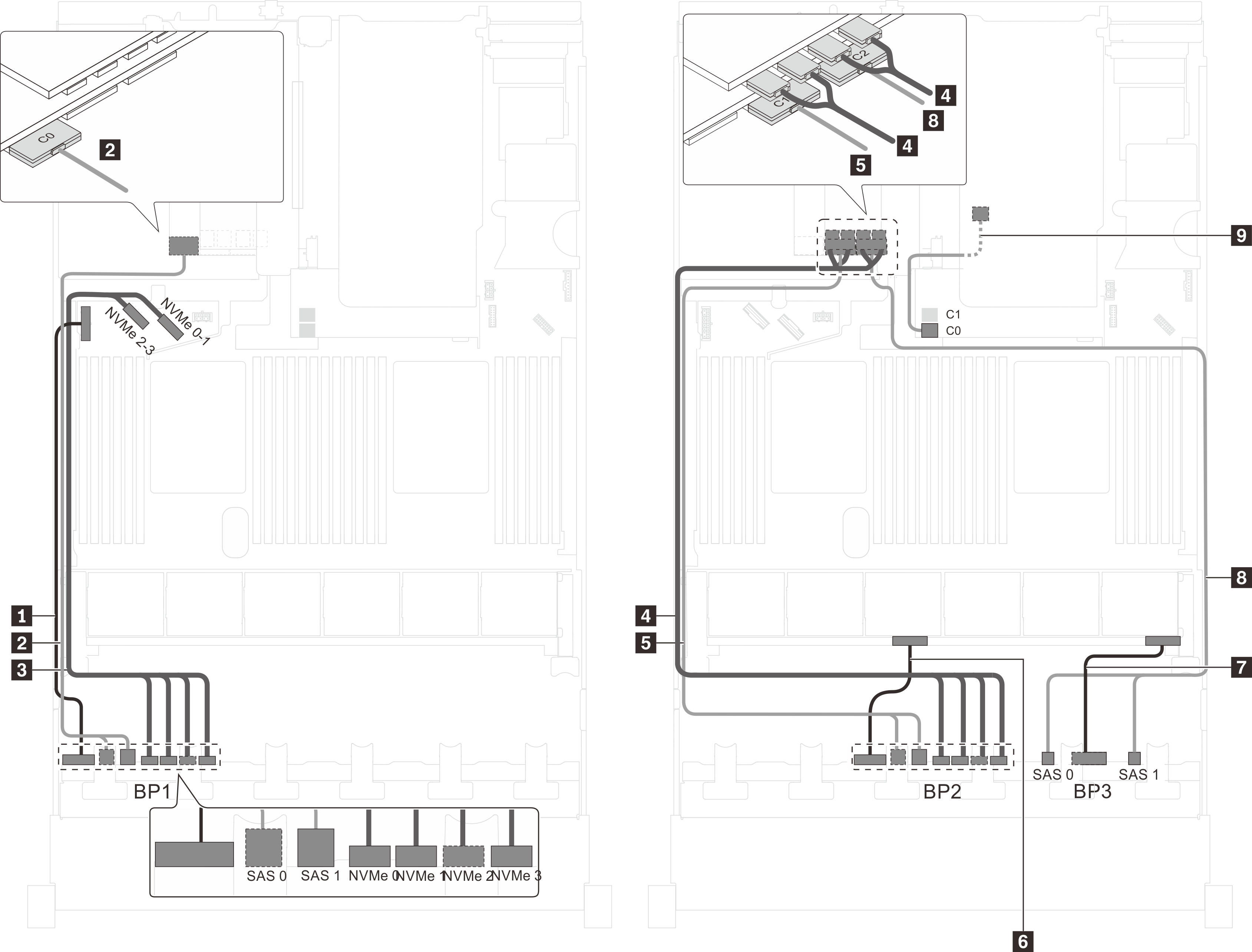
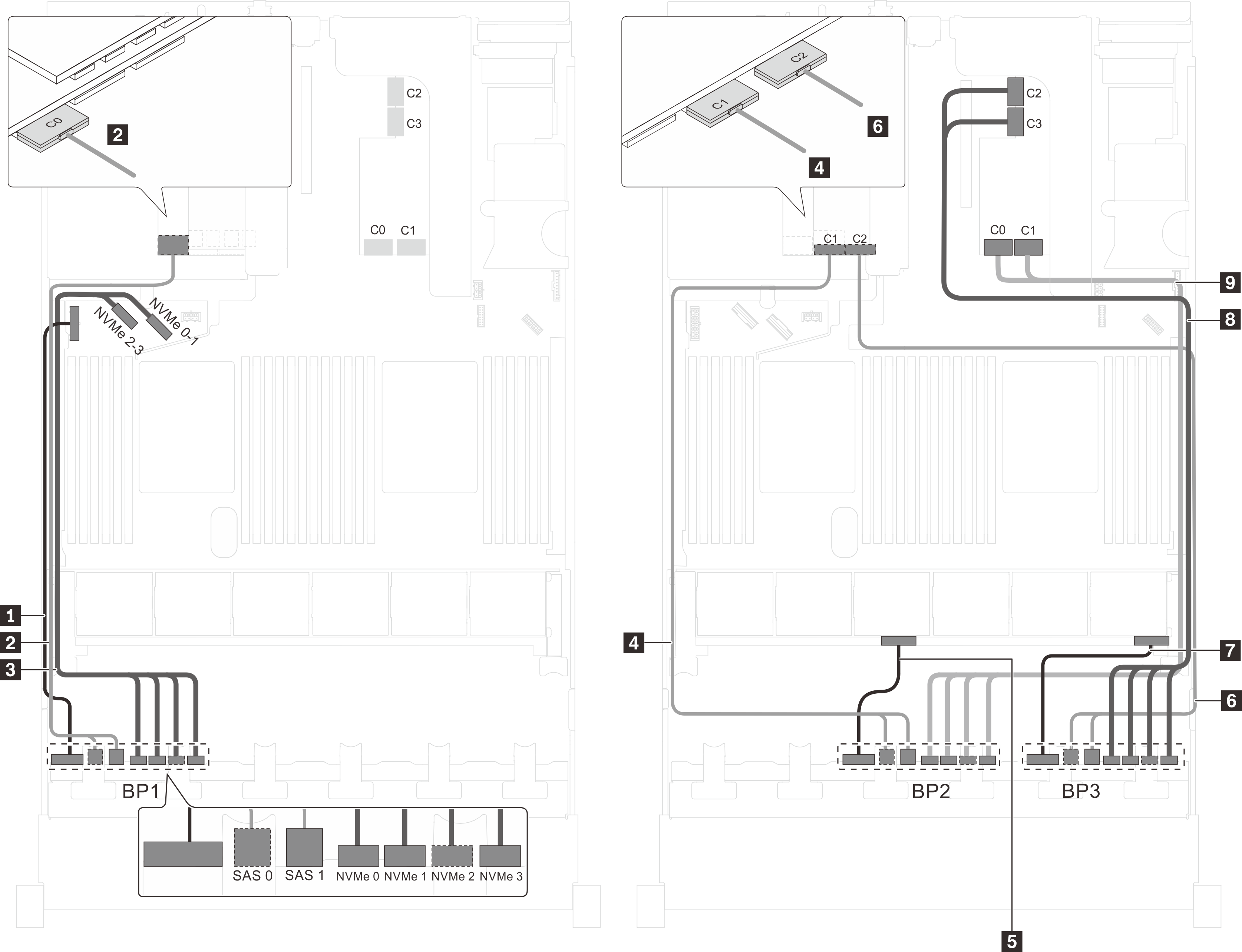
Server model: sixteen 2.5-inch SAS/SATA drives, eight 2.5-inch SAS/SATA/NVMe drives, one 24i RAID adapter, one NVMe switch adapter
| Cable | From | To |
|---|---|---|
| 1 Power cable for front backplane 1 | Power connector on front backplane 1 | Backplane power connector 1 on the system board |
| 2 SAS signal cable for front backplane 1 | SAS 0 and SAS 1 connectors on front backplane 1 | C0 and C1 connectors on the 24i RAID adapter on an available PCIe slot |
| 3 NVMe signal cable for front backplane 1 | NVMe 0, NVMe 1, NVMe 2, and NVMe 3 connectors on front backplane 1 | NVMe 0–1 and NVMe 2–3 connectors on the system board |
| 4 NVMe signal cable for front backplane 2 | NVMe 0, NVMe 1, NVMe 2, and NVMe 3 connectors on front backplane 2 | C0, C1, C2, and C3 connectors on the NVMe switch adapter on an available PCIe slot |
| 5 SAS signal cable for front backplane 2 | SAS 0 and SAS 1 connectors on front backplane 2 | C2 and C3 connectors on the 24i RAID adapter on an available PCIe slot |
| 6 Power cable for front backplane 2 | Power connector on front backplane 2 | Backplane power connector 2 on the system board |
| 7 Power cable for front backplane 3 | Power connector on front backplane 3 | Backplane power connector 3 on the system board |
| 8 SAS signal cable for front backplane 3 | SAS 0 and SAS 1 connectors on front backplane 3 | C4 and C5 connectors on the 24i RAID adapter on an available PCIe slot |
Server model: sixteen 2.5-inch SAS/SATA drives, eight 2.5-inch SAS/SATA/NVMe drives, one 32i RAID adapter, one NVMe switch adapter
Gen 4 HBA/RAID adapter cannot be installed in the inner raid adapter slot.
*Ensure you use Gen 4 SAS signal cable (ThinkSystem SR550/SR590/SR650 2.5" SAS/SATA/AnyBay 8-Bay X40 RAID Cable Kit).
| Cable | From | To |
|---|---|---|
| 1 Power cable for front backplane 1 | Power connector on front backplane 1 | Backplane power connector 1 on the system board |
| 2 SAS signal cable for front backplane 1* | SAS 0 and SAS 1 connectors on front backplane 1 | C0 connector on the 32i RAID adapter on an available PCIe slot |
| 3 NVMe signal cable for front backplane 1 | NVMe 0, NVMe 1, NVMe 2, and NVMe 3 connectors on front backplane 1 | NVMe 0–1 and NVMe 2–3 connectors on the system board |
| 4 NVMe signal cable for front backplane 2 | NVMe 0, NVMe 1, NVMe 2, and NVMe 3 connectors on front backplane 2 | C0, C1, C2, and C3 connectors on the NVMe switch adapter on an available PCIe slot |
| 5 SAS signal cable for front backplane 2* | SAS 0 and SAS 1 connectors on front backplane 2 | C1 connector on the 32i RAID adapter on an available PCIe slot |
| 6 Power cable for front backplane 2 | Power connector on front backplane 2 | Backplane power connector 2 on the system board |
| 7 Power cable for front backplane 3 | Power connector on front backplane 3 | Backplane power connector 3 on the system board |
| 8 SAS signal cable for front backplane 3* | SAS 0 and SAS 1 connectors on front backplane 3 | C2 connector on the 32i RAID adapter on an available PCIe slot |
Server model: sixteen 2.5-inch SAS/SATA drives, eight 2.5-inch SAS/SATA/NVMe drives, one 32i HBA/RAID adapter, one NVMe 1611-8P switch adapter
Gen 4 HBA/RAID adapter cannot be installed in the inner raid adapter slot.
*Ensure you use Gen 4 SAS signal cable (ThinkSystem SR550/SR590/SR650 2.5" SAS/SATA/AnyBay 8-Bay X40 RAID Cable Kit).
| Cable | From | To |
|---|---|---|
| 1 Power cable for front backplane 1 | Power connector on front backplane 1 | Backplane power connector 1 on the system board |
| 2 SAS signal cable for front backplane 1* | SAS 0 and SAS 1 connectors on front backplane 1 | C0 connector on the 32i RAID adapter on an available PCIe slot |
| 3 NVMe signal cable for front backplane 1 | NVMe 0, NVMe 1, NVMe 2, and NVMe 3 connectors on front backplane 1 | C2 and C3 connectors on the NVMe 1611–8P switch adapter installed in PCIe slot 1 |
| 4 SAS signal cable for front backplane 2* | SAS 0 and SAS 1 connectors on front backplane 2 | C1 connector on the 32i RAID adapter on an available PCIe slot |
| 5 Power cable for front backplane 2 | Power connector on front backplane 2 | Backplane power connector 2 on the system board |
| 6 Power cable for front backplane 3 | Power connector on front backplane 3 | Backplane power connector 3 on the system board |
| 7 SAS signal cable for front backplane 3* | SAS 0 and SAS 1 connectors on front backplane 3 | C2 connector on the 32i RAID adapter on an available PCIe slot |
| 8 NVMe signal cable for front backplane 2 | NVMe 0, NVMe 1, NVMe 2, and NVMe 3 connectors on front backplane 2 | C0 and C1 connectors on the NVMe 1611–8P switch adapter installed in PCIe slot 1 |
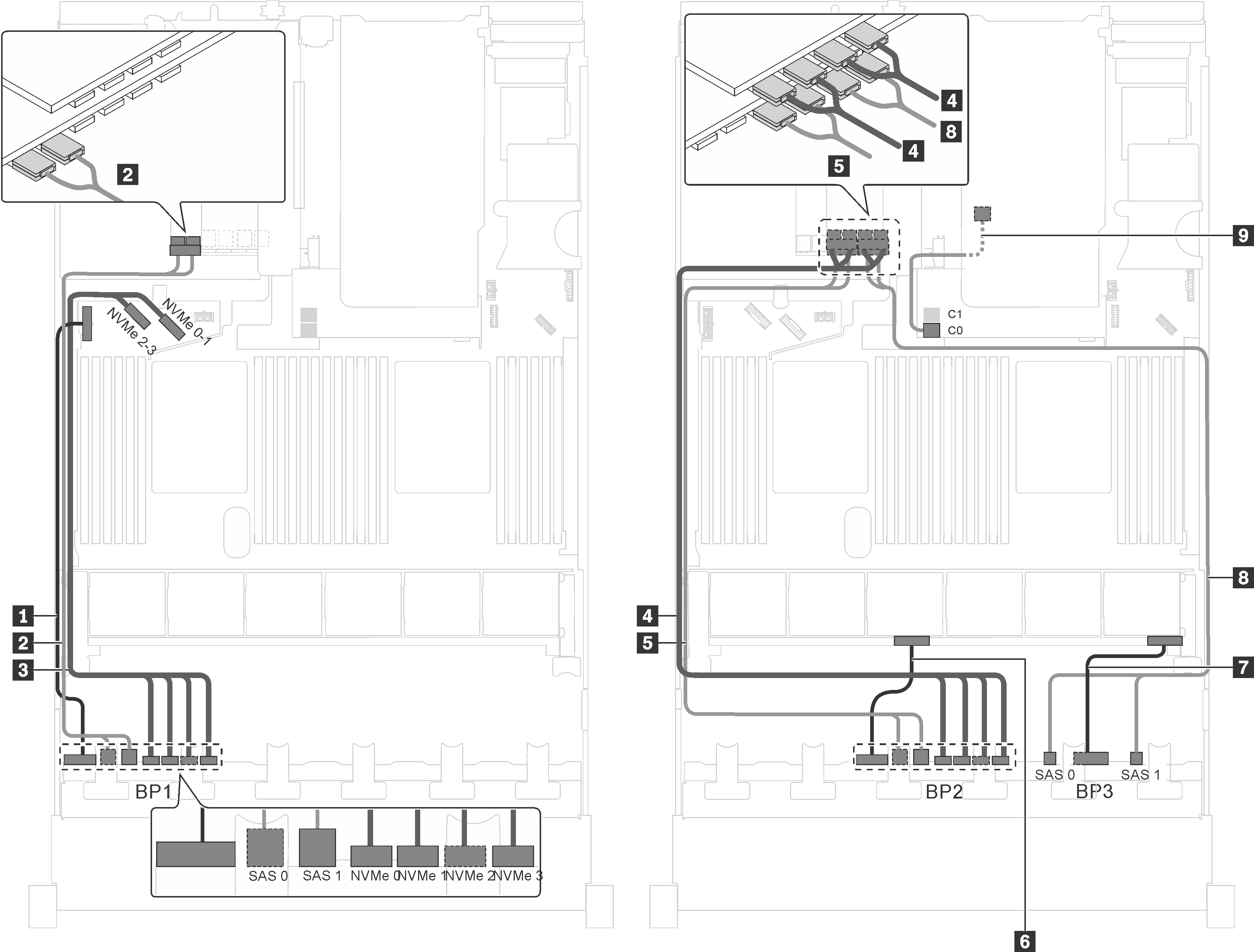
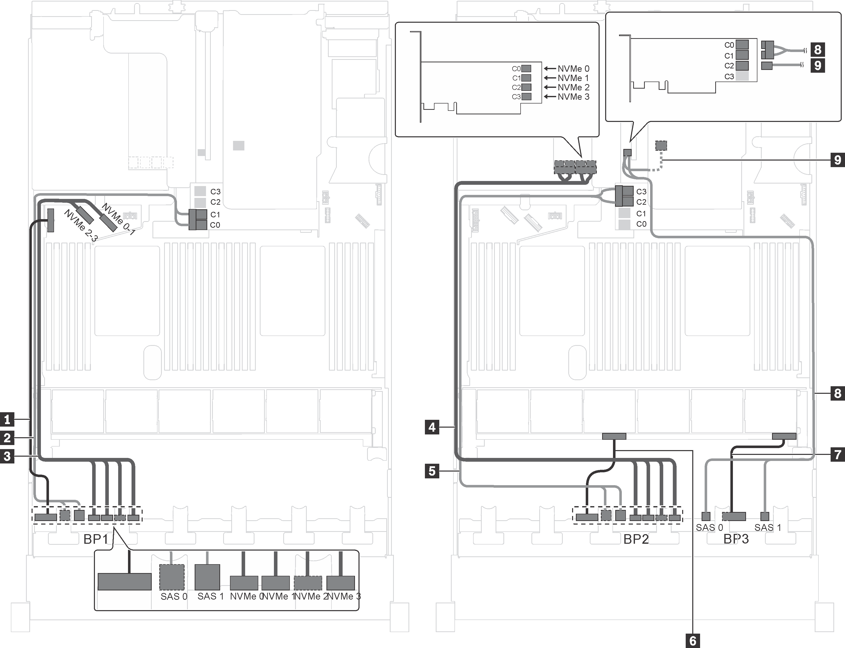
Server model: sixteen 2.5-inch SAS/SATA drives, eight 2.5-inch SAS/SATA/NVMe drives, the rear hot-swap drive assembly, one 8i HBA/RAID adapter, one 24i RAID adapter, one NVMe switch adapter
Gen 4 HBA/RAID adapter cannot be installed in the inner raid adapter slot.
*When Gen 4 HBA/RAID adapter is installed, ensure you use Gen 4 SAS signal cable (ThinkSystem SR590/SR650 3.5" SAS/SATA 2-Bay Rear BP X40 RAID Cable Kit).
| Cable | From | To |
|---|---|---|
| 1 Power cable for front backplane 1 | Power connector on front backplane 1 | Backplane power connector 1 on the system board |
| 2 SAS signal cable for front backplane 1 | SAS 0 and SAS 1 connectors on front backplane 1 | C0 and C1 connectors on the 24i RAID adapter installed in PCIe slot 6 |
| 3 NVMe signal cable for front backplane 1 | NVMe 0, NVMe 1, NVMe 2, and NVMe 3 connectors on front backplane 1 | NVMe 0–1 and NVMe 2–3 connectors on the system board |
| 4 NVMe signal cable for front backplane 2 | NVMe 0, NVMe 1, NVMe 2, and NVMe 3 connectors on front backplane 2 | C0, C1, C2, and C3 connectors on the NVMe switch adapter installed in PCIe slot 5 |
| 5 SAS signal cable for front backplane 2 | SAS 0 and SAS 1 connectors on front backplane 2 | C2 and C3 connectors on the 24i RAID adapter installed in PCIe slot 6 |
| 6 Power cable for front backplane 2 | Power connector on front backplane 2 | Backplane power connector 2 on the system board |
| 7 Power cable for front backplane 3 | Power connector on front backplane 3 | Backplane power connector 3 on the system board |
| 8 SAS signal cable for front backplane 3 | SAS 0 and SAS 1 connectors on front backplane 3 | C4 and C5 connectors on the 24i RAID adapter installed in PCIe slot 6 |
| 9 SAS signal cable for the rear hot-swap drive assembly* | Signal connector on the rear hot-swap drive assembly | 8i HBA/RAID adapter on the RAID adapter slot
|
Server model: sixteen 2.5-inch SAS/SATA drives, eight 2.5-inch SAS/SATA/NVMe drives, one 8i HBA/RAID adapter, one 16i HBA/RAID adapter, one NVMe 1611-8P switch adapter
| Cable | From | To |
|---|---|---|
| 1 Power cable for front backplane 1 | Power connector on front backplane 1 | Backplane power connector 1 on the system board |
| 2 SAS signal cable for front backplane 1 | SAS 0 and SAS 1 connectors on front backplane 1 | 8i HBA/RAID adapter on the RAID adapter slot
|
| 3 NVMe signal cable for front backplane 1 | NVMe 0, NVMe 1, NVMe 2, and NVMe 3 connectors on front backplane 1 | C2 and C3 connectors on the NVMe 1611–8P switch adapter installed in PCIe slot 1 |
| 4 SAS signal cable for front backplane 2 | SAS 0 and SAS 1 connectors on front backplane 2 | 16i HBA/RAID adapter installed in PCIe slot 1
|
| 5 Power cable for front backplane 2 | Power connector on front backplane 2 | Backplane power connector 2 on the system board |
| 6 Power cable for front backplane 3 | Power connector on front backplane 3 | Backplane power connector 3 on the system board |
| 7 SAS signal cable for front backplane 3 | SAS 0 and SAS 1 connectors on front backplane 3 | 16i HBA/RAID adapter installed in PCIe slot 1
|
| 8 NVMe signal cable for front backplane 2 | NVMe 0, NVMe 1, NVMe 2, and NVMe 3 connectors on front backplane 2 | C0 and C1 connectors on the NVMe 1611–8P switch adapter installed in PCIe slot 1 |
Server model: sixteen 2.5-inch SAS/SATA drives, eight 2.5-inch SAS/SATA/NVMe drives, the rear hot-swap drive assembly, one 8i HBA/RAID adapter, one 32i RAID adapter, one NVMe switch adapter
Gen 4 HBA/RAID adapter cannot be installed in the inner raid adapter slot.
- *When Gen 4 HBA/RAID adapter is installed, ensure you use Gen 4 SAS signal cable:
Cable 2/5/8: ThinkSystem SR550/SR590/SR650 2.5" SAS/SATA/AnyBay 8-Bay X40 RAID Cable Kit
Cable 9: ThinkSystem SR590/SR650 3.5" SAS/SATA 2-Bay Rear BP X40 RAID Cable Kit
| Cable | From | To |
|---|---|---|
| 1 Power cable for front backplane 1 | Power connector on front backplane 1 | Backplane power connector 1 on the system board |
| 2 SAS signal cable for front backplane 1* | SAS 0 and SAS 1 connectors on front backplane 1 | C0 connector on the 32i RAID adapter on PCIe slot 6 |
| 3 NVMe signal cable for front backplane 1 | NVMe 0, NVMe 1, NVMe 2, and NVMe 3 connectors on front backplane 1 | NVMe 0–1 and NVMe 2–3 connectors on the system board |
| 4 NVMe signal cable for front backplane 2 | NVMe 0, NVMe 1, NVMe 2, and NVMe 3 connectors on front backplane 2 | C0, C1, C2, and C3 connectors on the NVMe switch adapter installed in PCIe slot 5 |
| 5 SAS signal cable for front backplane 2* | SAS 0 and SAS 1 connectors on front backplane 2 | C1 connector on the 32i RAID adapter on PCIe slot 6 |
| 6 Power cable for front backplane 2 | Power connector on front backplane 2 | Backplane power connector 2 on the system board |
| 7 Power cable for front backplane 3 | Power connector on front backplane 3 | Backplane power connector 3 on the system board |
| 8 SAS signal cable for front backplane 3* | SAS 0 and SAS 1 connectors on front backplane 3 | C2 connector on the 32i RAID adapter on PCIe slot 6 |
| 9 SAS signal cable for the rear hot-swap drive assembly* | Signal connector on the rear hot-swap drive assembly | 8i HBA/RAID adapter on the RAID adapter slot
|
Server model: sixteen 2.5-inch SAS/SATA drives, eight 2.5-inch SAS/SATA/NVMe drives, the rear hot-swap drive assembly, two 16i HBA/RAID adapters, one NVMe switch adapter
Gen 4 HBA/RAID adapter cannot be installed in the inner raid adapter slot.
- *When Gen 4 HBA/RAID adapter is installed, ensure you use Gen 4 SAS signal cable:
Cable 2/5/8: ThinkSystem SR550/SR590/SR650 2.5" SAS/SATA/AnyBay 8-Bay X40 RAID Cable Kit
Cable 9: ThinkSystem SR590/SR650 3.5" SAS/SATA 2-Bay Rear BP X40 RAID Cable Kit
| Cable | From | To |
|---|---|---|
| 1 Power cable for front backplane 1 | Power connector on front backplane 1 | Backplane power connector 1 on the system board |
| 2 SAS signal cable for front backplane 1* | SAS 0 and SAS 1 connectors on front backplane 1 | 16i HBA/RAID adapter on the RAID adapter slot
|
| 3 NVMe signal cable for front backplane 1 | NVMe 0, NVMe 1, NVMe 2, and NVMe 3 connectors on front backplane 1 | NVMe 0–1 and NVMe 2–3 connectors on the system board |
| 4 NVMe signal cable for front backplane 2 | NVMe 0, NVMe 1, NVMe 2, and NVMe 3 connectors on front backplane 2 | C0, C1, C2, and C3 connectors on the NVMe switch adapter installed in PCIe slot 5 |
| 5 SAS signal cable for front backplane 2* | SAS 0 and SAS 1 connectors on front backplane 2 | 16i HBA/RAID adapter on the RAID adapter slot
|
| 6 Power cable for front backplane 2 | Power connector on front backplane 2 | Backplane power connector 2 on the system board |
| 7 Power cable for front backplane 3 | Power connector on front backplane 3 | Backplane power connector 3 on the system board |
| 8 SAS signal cable for front backplane 3* | SAS 0 and SAS 1 connectors on front backplane 3 | 16i HBA/RAID adapter on PCIe slot 4
|
| 9 SAS signal cable for the rear hot-swap drive assembly* | Signal connector on the rear hot-swap drive assembly | 16i HBA/RAID adapter on PCIe slot 4
|
Server model: sixteen 2.5-inch SAS/SATA drives, eight 2.5-inch SAS/SATA/NVMe drives, the rear hot-swap drive assembly, two 8i HBA/RAID adapters, one 16i HBA/RAID adapter, one NVMe switch adapter
The cable routing illustration is based on the scenario that the rear hot-swap drive assembly is installed. Depending on the model, the rear hot-swap drive assembly and the cable 6 might not be available on your server.
Gen 4 HBA/RAID adapter cannot be installed in the inner raid adapter slot.
- *When Gen 4 HBA/RAID adapter is installed, ensure you use Gen 4 SAS signal cable:
Cable 2/5/7: ThinkSystem SR550/SR590/SR650 2.5" SAS/SATA/AnyBay 8-Bay X40 RAID Cable Kit
Cable 6: ThinkSystem SR590/SR650 3.5" SAS/SATA 2-Bay Rear BP X40 RAID Cable Kit
| Cable | From | To |
|---|---|---|
| 1 Power cable for front backplane 1 | Power connector on front backplane 1 | Backplane power connector 1 on the system board |
| 2 SAS signal cable for front backplane 1* | SAS 0 and SAS 1 connectors on front backplane 1 | 8i HBA/RAID adapter on the RAID adapter slot
|
| 3 NVMe signal cable for front backplane 1 | NVMe 0, NVMe 1, NVMe 2, and NVMe 3 connectors on front backplane 1 | NVMe 0–1 and NVMe 2–3 connectors on the system board |
| 4 Power cable for front backplane 3 | Power connector on front backplane 3 | Backplane power connector 3 on the system board |
| 5 SAS signal cable for front backplane 3* | SAS 0 and SAS 1 connectors on front backplane 3 | 16i HBA/RAID adapter on PCIe slot 6
|
| 6 SAS signal cable for the rear hot-swap drive assembly* | Signal connector on the rear hot-swap drive assembly | 16i HBA/RAID adapter on PCIe slot 6
|
| 7 SAS signal cable for front backplane 2* | SAS 0 and SAS 1 connectors on front backplane 2 | 8i HBA/RAID adapter on PCIe slot 4
|
| 8 NVMe signal cable for front backplane 2 | NVMe 0, NVMe 1, NVMe 2, and NVMe 3 connectors on front backplane 2 | C0, C1, C2, and C3 connectors on the NVMe switch adapter installed in PCIe slot 5 |
| 9 Power cable for front backplane 2 | Power connector on front backplane 2 | Backplane power connector 2 on the system board |
Server model: twelve 2.5-inch SAS/SATA drives, twelve 2.5-inch SAS/SATA/NVMe drives, one 24i RAID adapter, two NVMe switch adapters
| Cable | From | To |
|---|---|---|
| 1 Power cable for front backplane 1 | Power connector on front backplane 1 | Backplane power connector 1 on the system board |
| 2 SAS signal cable for front backplane 1 | SAS 0 and SAS 1 connectors on front backplane 1 | C0 and C1 connectors on the 24i RAID adapter installed in PCIe slot 6 |
| 3 NVMe signal cable for front backplane 1 | NVMe 0, NVMe 1, NVMe 2, and NVMe 3 connectors on front backplane 1 | NVMe 0–1 and NVMe 2–3 connectors on the system board |
| 4 NVMe signal cable for front backplane 2 | NVMe 0, NVMe 1, NVMe 2, and NVMe 3 connectors on front backplane 2 | C0, C1, C2, and C3 connectors on the NVMe switch adapter installed in PCIe slot 5 |
| 5 SAS signal cable for front backplane 2 | SAS 0 and SAS 1 connectors on front backplane 2 | C2 and C3 connectors on the 24i RAID adapter installed in PCIe slot 6 |
| 6 Power cable for front backplane 2 | Power connector on front backplane 2 | Backplane power connector 2 on the system board |
| 7 SAS signal cable for front backplane 3 | SAS 0 and SAS 1 connectors on front backplane 3 | C4 and C5 connectors on the 24i RAID adapter installed in PCIe slot 6 |
| 8 Power cable for front backplane 3 | Power connector on front backplane 3 | Backplane power connector 3 on the system board |
| 9 NVMe signal cable for front backplane 3 | NVMe 0, NVMe 1, NVMe 2, and NVMe 3 connectors on front backplane 3 | C0, C1, C2, and C3 connectors on the NVMe switch adapter installed in PCIe slot 1 |
Server model: twelve 2.5-inch SAS/SATA drives, twelve 2.5-inch SAS/SATA/NVMe drives, one 32i RAID adapter, two NVMe switch adapters
Gen 4 HBA/RAID adapter cannot be installed in the inner raid adapter slot.
*Ensure you use Gen 4 SAS signal cable (ThinkSystem SR550/SR590/SR650 2.5" SAS/SATA/AnyBay 8-Bay X40 RAID Cable Kit).
| Cable | From | To |
|---|---|---|
| 1 Power cable for front backplane 1 | Power connector on front backplane 1 | Backplane power connector 1 on the system board |
| 2 SAS signal cable for front backplane 1* | SAS 0 and SAS 1 connectors on front backplane 1 | C0 connector on the 32i RAID adapter on PCIe slot 6 |
| 3 NVMe signal cable for front backplane 1 | NVMe 0, NVMe 1, NVMe 2, and NVMe 3 connectors on front backplane 1 | NVMe 0–1 and NVMe 2–3 connectors on the system board |
| 4 NVMe signal cable for front backplane 2 | NVMe 0, NVMe 1, NVMe 2, and NVMe 3 connectors on front backplane 2 | C0, C1, C2, and C3 connectors on the NVMe switch adapter installed in PCIe slot 5 |
| 5 SAS signal cable for front backplane 2* | SAS 0 and SAS 1 connectors on front backplane 2 | C1 connector on the 32i RAID adapter on PCIe slot 6 |
| 6 Power cable for front backplane 2 | Power connector on front backplane 2 | Backplane power connector 2 on the system board |
| 7 SAS signal cable for front backplane 3* | SAS 0 and SAS 1 connectors on front backplane 3 | C2 connector on the 32i RAID adapter on PCIe slot 6 |
| 8 Power cable for front backplane 3 | Power connector on front backplane 3 | Backplane power connector 3 on the system board |
| 9 NVMe signal cable for front backplane 3 | NVMe 0, NVMe 1, NVMe 2, and NVMe 3 connectors on front backplane 3 | C0, C1, C2, and C3 connectors on the NVMe switch adapter installed in PCIe slot 1 |
Server model: twelve 2.5-inch SAS/SATA drives, twelve 2.5-inch SAS/SATA/NVMe drives, one 32i HBA/RAID adapter, one NVMe 1611-8P switch adapter
Gen 4 HBA/RAID adapter cannot be installed in the inner raid adapter slot.
*Ensure you use Gen 4 SAS signal cable (ThinkSystem SR550/SR590/SR650 2.5" SAS/SATA/AnyBay 8-Bay X40 RAID Cable Kit).
| Cable | From | To |
|---|---|---|
| 1 Power cable for front backplane 1 | Power connector on front backplane 1 | Backplane power connector 1 on the system board |
| 2 SAS signal cable for front backplane 1* | SAS 0 and SAS 1 connectors on front backplane 1 | C0 connector on the 32i RAID adapter on PCIe slot 6 |
| 3 NVMe signal cable for front backplane 1 | NVMe 0, NVMe 1, NVMe 2, and NVMe 3 connectors on front backplane 1 | NVMe 0–1 and NVMe 2–3 connectors on the system board |
| 4 SAS signal cable for front backplane 2* | SAS 0 and SAS 1 connectors on front backplane 2 | C1 connector on the 32i RAID adapter on PCIe slot 6 |
| 5 Power cable for front backplane 2 | Power connector on front backplane 2 | Backplane power connector 2 on the system board |
| 6 SAS signal cable for front backplane 3* | SAS 0 and SAS 1 connectors on front backplane 3 | C2 connector on the 32i RAID adapter on PCIe slot 6 |
| 7 Power cable for front backplane 3 | Power connector on front backplane 3 | Backplane power connector 3 on the system board |
| 8 NVMe signal cable for front backplane 3 | NVMe 0, NVMe 1, NVMe 2, and NVMe 3 connectors on front backplane 3 | C2 and C3 connectors on the NVMe 1611–8P installed in PCIe slot 1 |
| 9 NVMe signal cable for front backplane 2 | NVMe 0, NVMe 1, NVMe 2, and NVMe 3 connectors on front backplane 2 | C0 and C1 connectors on the NVMe 1611–8P installed in PCIe slot 1 |
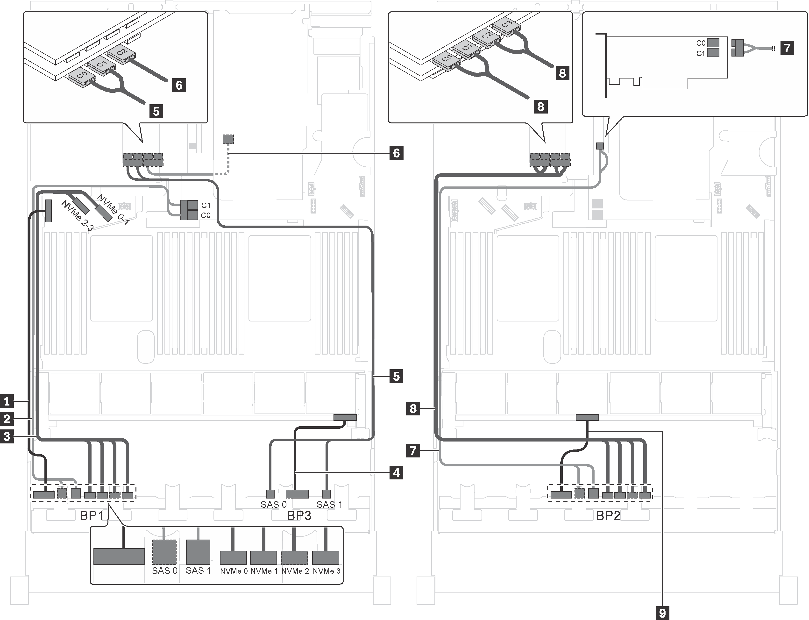
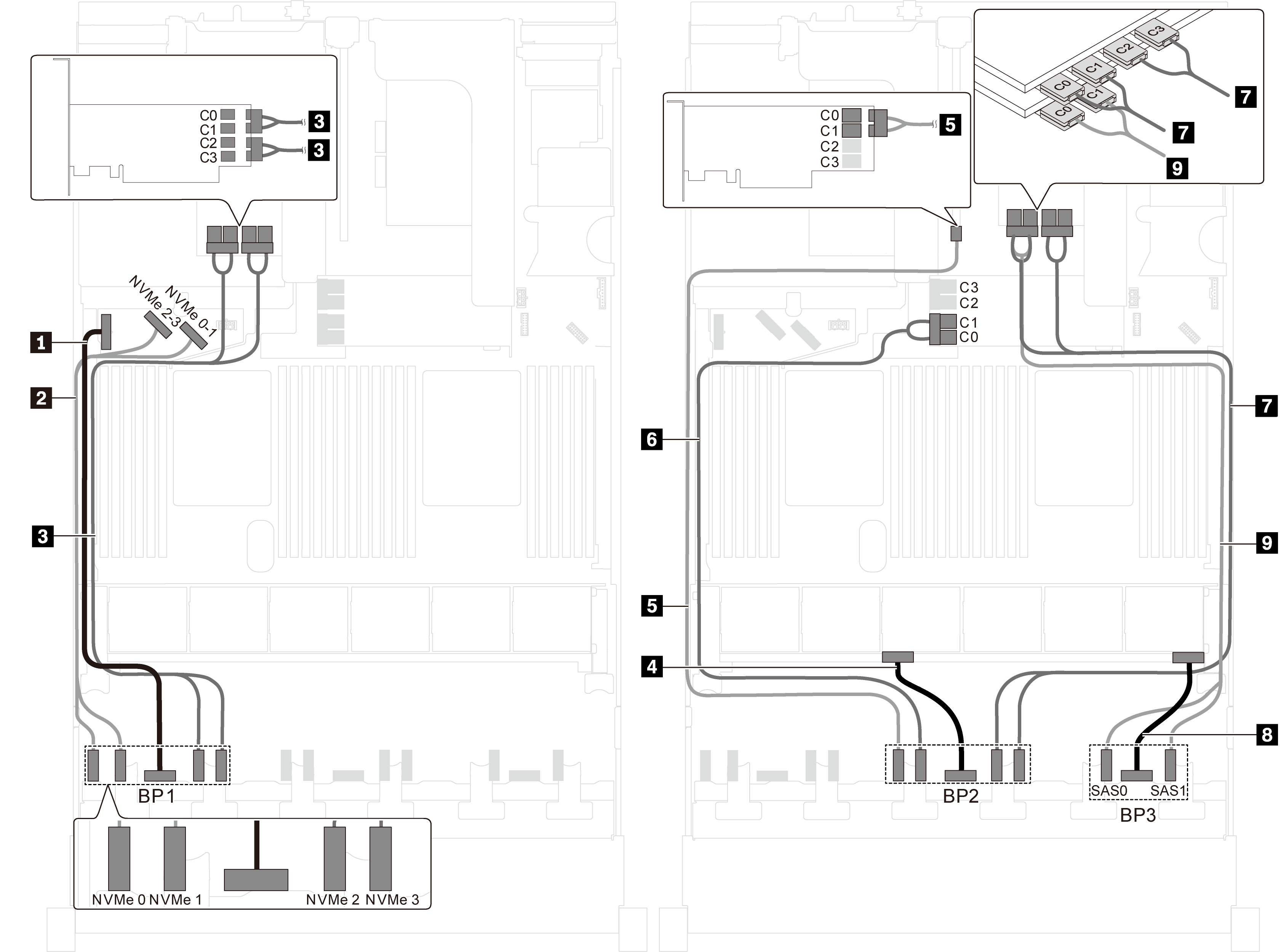
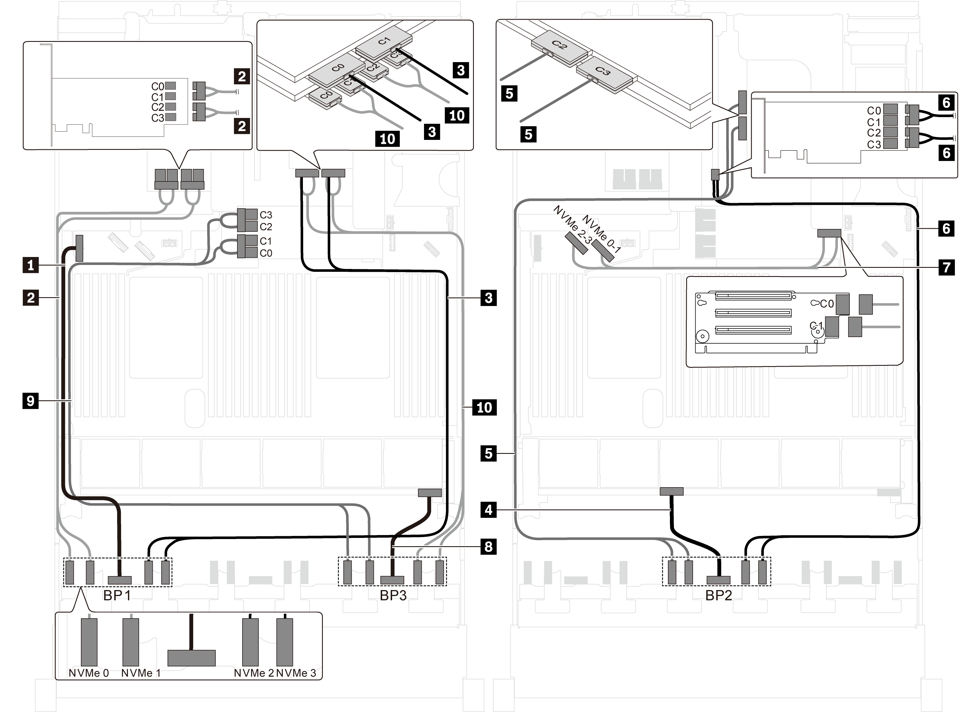
Server model: twelve 2.5-inch SAS/SATA drives, twelve 2.5-inch SAS/SATA/NVMe drives, three 8i HBA/RAID adapters, two NVMe switch adapters
Gen 4 HBA/RAID adapter cannot be installed in the inner raid adapter slot.
*When Gen 4 HBA/RAID adapter is installed, ensure you use Gen 4 SAS signal cable (ThinkSystem SR550/SR590/SR650 2.5" SAS/SATA/AnyBay 8-Bay X40 RAID Cable Kit).
| Cable | From | To |
|---|---|---|
| 1 Power cable for front backplane 1 | Power connector on front backplane 1 | Backplane power connector 1 on the system board |
| 2 SAS signal cable for front backplane 1* | SAS 0 and SAS 1 connectors on front backplane 1 | 8i HBA/RAID adapter on the RAID adapter slot
|
| 3 NVMe signal cable for front backplane 1 | NVMe 0, NVMe 1, NVMe 2, and NVMe 3 connectors on front backplane 1 | NVMe 0–1 and NVMe 2–3 connectors on the system board |
| 4 Power cable for front backplane 3 | Power connector on front backplane 3 | Backplane power connector 3 on the system board |
| 5 SAS signal cable for front backplane 3* | SAS 0 and SAS 1 connectors on front backplane 3 | 8i HBA/RAID adapter on PCIe slot 2
|
| 6 NVMe signal cable for front backplane 3 | NVMe 0, NVMe 1, NVMe 2, and NVMe 3 connectors on front backplane 3 | C0, C1, C2, and C3 connectors on the NVMe switch adapter installed in PCIe slot 1 |
| 7 SAS signal cable for front backplane 2* | SAS 0 and SAS 1 connectors on front backplane 2 | 8i HBA/RAID adapter on PCIe slot 4
|
| 8 NVMe signal cable for front backplane 2 | NVMe 0, NVMe 1, NVMe 2, and NVMe 3 connectors on front backplane 2 | C0, C1, C2, and C3 connectors on the NVMe switch adapter installed in PCIe slot 5 |
| 9 Power cable for front backplane 2 | Power connector on front backplane 2 | Backplane power connector 2 on the system board |
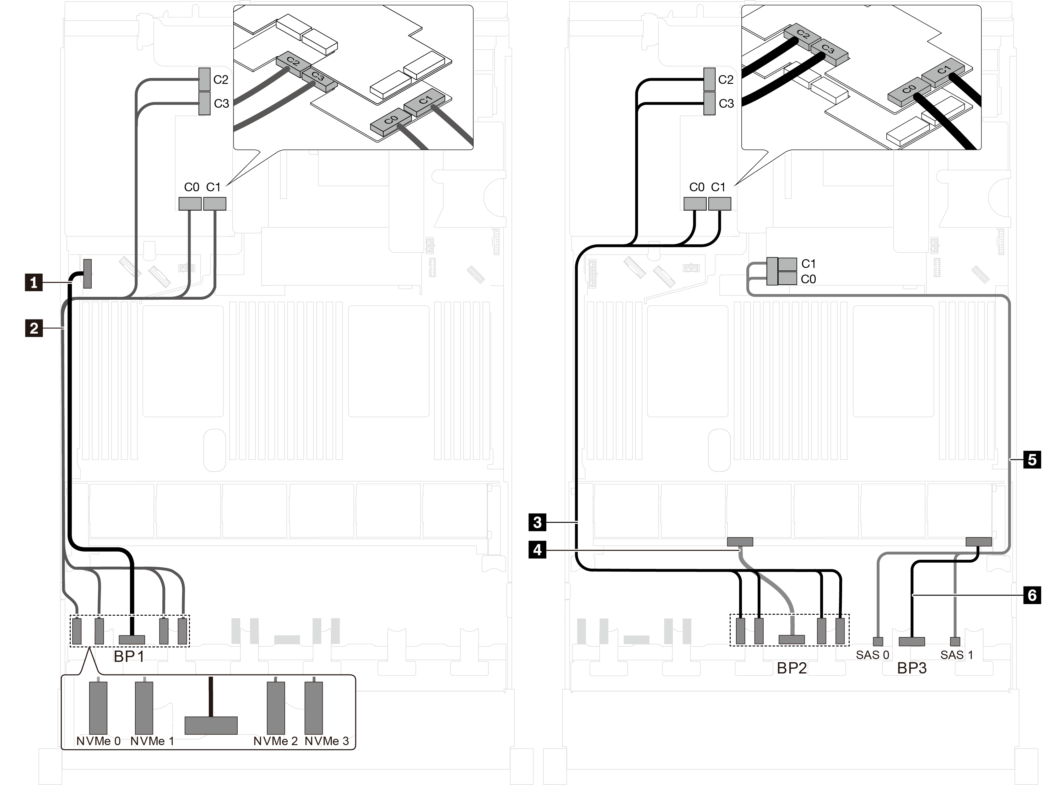
Server model: twelve 2.5-inch SAS/SATA drives, twelve 2.5-inch SAS/SATA/NVMe drives, one 8i HBA/RAID adapter, one 16i HBA/RAID adapters, two NVMe switch adapters
Gen 4 HBA/RAID adapter cannot be installed in the inner raid adapter slot.
*When Gen 4 HBA/RAID adapter is installed, ensure you use Gen 4 SAS signal cable (ThinkSystem SR550/SR590/SR650 2.5" SAS/SATA/AnyBay 8-Bay X40 RAID Cable Kit).
| Cable | From | To |
|---|---|---|
| 1 Power cable for front backplane 1 | Power connector on front backplane 1 | Backplane power connector 1 on the system board |
| 2 SAS signal cable for front backplane 1* | SAS 0 and SAS 1 connectors on front backplane 1 | 8i HBA/RAID adapter on the RAID adapter slot
|
| 3 NVMe signal cable for front backplane 1 | NVMe 0, NVMe 1, NVMe 2, and NVMe 3 connectors on front backplane 1 | NVMe 0–1 and NVMe 2–3 connectors on the system board |
| 4 Power cable for front backplane 3 | Power connector on front backplane 3 | Backplane power connector 3 on the system board |
| 5 SAS signal cable for front backplane 3* | SAS 0 and SAS 1 connectors on front backplane 3 | 16i HBA/RAID adapter on PCIe slot 4
|
| 6 NVMe signal cable for front backplane 3 | NVMe 0, NVMe 1, NVMe 2, and NVMe 3 connectors on front backplane 3 | C0, C1, C2, and C3 connectors on the NVMe switch adapter installed in PCIe slot 1 |
| 7 SAS signal cable for front backplane 2* | SAS 0 and SAS 1 connectors on front backplane 2 | 16i HBA/RAID adapter on PCIe slot 4
|
| 8 NVMe signal cable for front backplane 2 | NVMe 0, NVMe 1, NVMe 2, and NVMe 3 connectors on front backplane 2 | C0, C1, C2, and C3 connectors on the NVMe switch adapter installed in PCIe slot 5 |
| 9 Power cable for front backplane 2 | Power connector on front backplane 2 | Backplane power connector 2 on the system board |
Server model: twelve 2.5-inch SAS/SATA drives, twelve 2.5-inch SAS/SATA/NVMe drives, one 8i HBA/RAID adapter, one 16i HBA/RAID adapter, one NVMe 1611-8P switch adapter
Gen 4 HBA/RAID adapter cannot be installed in the inner raid adapter slot.
*When Gen 4 HBA/RAID adapter is installed, ensure you use Gen 4 SAS signal cable (ThinkSystem SR550/SR590/SR650 2.5" SAS/SATA/AnyBay 8-Bay X40 RAID Cable Kit).
| Cable | From | To |
|---|---|---|
| 1 Power cable for front backplane 1 | Power connector on front backplane 1 | Backplane power connector 1 on the system board |
| 2 SAS signal cable for front backplane 1* | SAS 0 and SAS 1 connectors on front backplane 1 | 8i HBA/RAID adapter on the RAID adapter slot
|
| 3 NVMe signal cable for front backplane 1 | NVMe 0, NVMe 1, NVMe 2, and NVMe 3 connectors on front backplane 1 | NVMe 0–1 and NVMe 2–3 connectors on the system board |
| 4 SAS signal cable for front backplane 3* | SAS 0 and SAS 1 connectors on front backplane 3 | 16i HBA/RAID adapter on PCIe slot 4
|
| 5 SAS signal cable for front backplane 2* | SAS 0 and SAS 1 connectors on front backplane 2 | 16i HBA/RAID adapter on PCIe slot 4
|
| 6 Power cable for front backplane 2 | Power connector on front backplane 2 | Backplane power connector 2 on the system board |
| 7 Power cable for front backplane 3 | Power connector on front backplane 3 | Backplane power connector 3 on the system board |
| 8 NVMe signal cable for front backplane 3 | NVMe 0, NVMe 1, NVMe 2, and NVMe 3 connectors on front backplane 3 | C2 and C3 connectors on the NVMe 1611–8P switch adapter installed in PCIe slot 1 |
| 9 NVMe signal cable for front backplane 2 | NVMe 0, NVMe 1, NVMe 2, and NVMe 3 connectors on front backplane 2 | C0 and C1 connectors on the NVMe 1611–8P switch adapter installed in PCIe slot 1 |
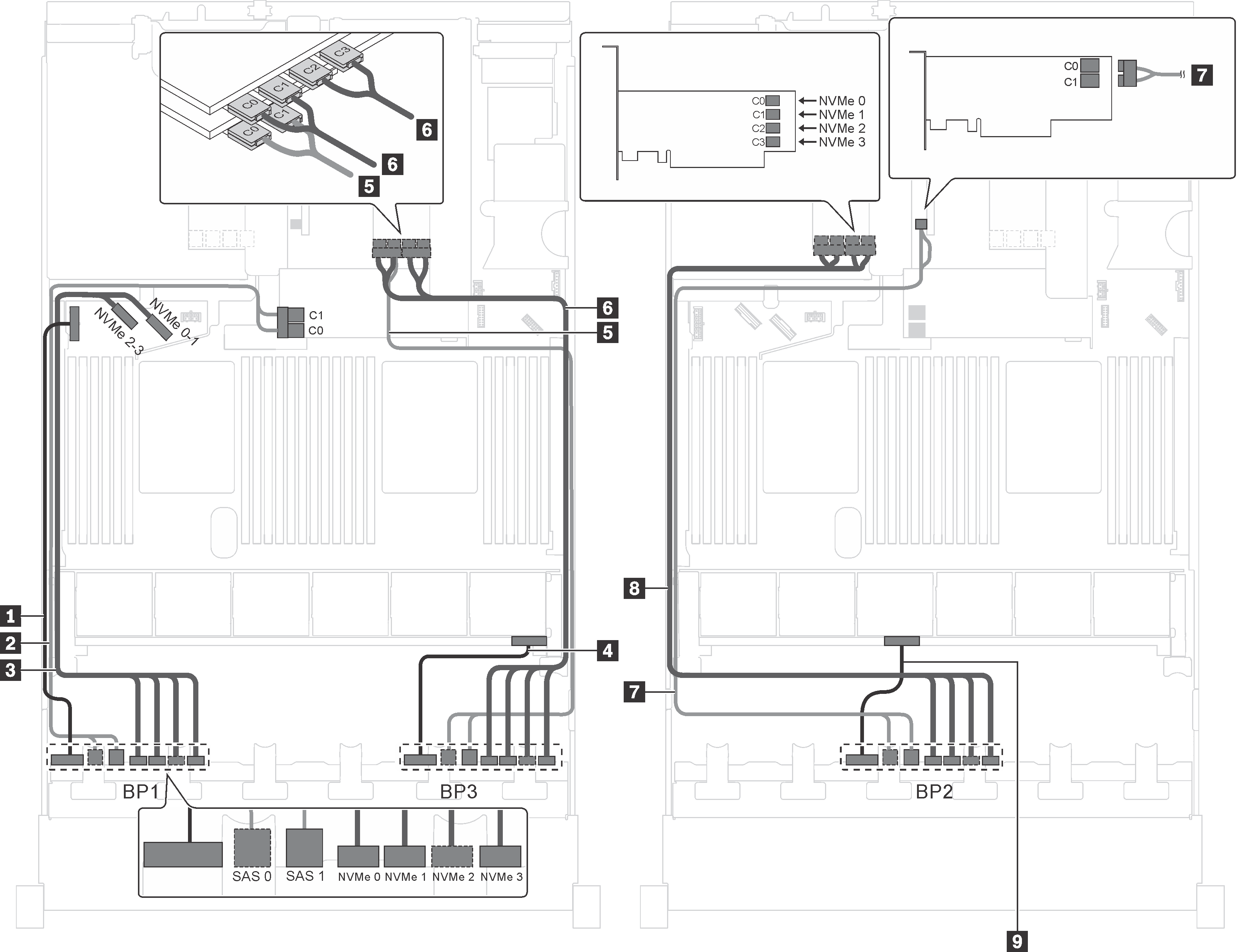
Server model: sixteen 2.5-inch NVMe drives, eight SAS/SATA drives, two NVMe 810-4P switch adapters, two NVMe 1610-4P switch adapters, one 8i HBA/RAID adapter
Gen 4 HBA/RAID adapter cannot be installed in the inner raid adapter slot.
*When Gen 4 HBA/RAID adapter is installed, ensure you use Gen 4 SAS signal cable (ThinkSystem SR550/SR590/SR650 2.5" SAS/SATA/AnyBay 8-Bay X40 RAID Cable Kit).
| Cable | From | To |
|---|---|---|
| 1 Power cable for front backplane 1 | Power connector on front backplane 1 | Backplane power connector 1 on the system board |
| 2 NVMe signal cable for front backplane 1 | NVMe 0 and NVMe 1 connectors on front backplane 1 | NVMe 2–3 and NVMe 0–1 connectors on the system board |
| 3 NVMe signal cable for front backplane 1 | NVMe 2 and NVMe 3 connectors on front backplane 1 | C0, C1, C2, and C3 connectors on the NVMe 1610-4P switch adapter installed in PCIe slot 6 |
| 4 Power cable for front backplane 2 | Power connector on front backplane 2 | Backplane power connector 2 on the system board |
| 5 NVMe signal cable for front backplane 2 | NVMe 0 connector on front backplane 2 | C0 and C1 connector on the NVMe 810-4P switch adapter installed in PCIe slot 4 |
| 6 NVMe signal cable for front backplane 2 | NVMe 1 connector on front backplane 2 | C0 and C1 connector on the NVMe 810-4P switch adapter installed in RAID adapter slot on the system board |
| 7 NVMe signal cable for front backplane 2 | NVMe 2 and NVMe 3 connectors on front backplane 2 | C0, C1, C2, and C3 connectors on the NVMe 1610-4P switch adapter installed in PCIe slot 1 |
| 8 Power cable for front backplane 3 | Power connector on front backplane 3 | Backplane power connector 3 on the system board |
| 9 SAS signal cable for front backplane 3* | SAS 0 and SAS 1 connectors on front backplane 3 | 8i HBA/RAID adapter on PCIe slot 3
|
Server model: sixteen 2.5-inch NVMe drives, eight 2.5-inch SAS/SATA drives, one 8i HBA/RAID adapter, two NVMe 1611-8P switch adapters
Gen 4 HBA/RAID adapter cannot be installed in the inner raid adapter slot.
*When Gen 4 HBA/RAID adapter is installed, ensure you use Gen 4 SAS signal cable (ThinkSystem SR550/SR590/SR650 2.5" SAS/SATA/AnyBay 8-Bay X40 RAID Cable Kit).
| Cable | From | To |
|---|---|---|
| 1 Power cable for front backplane 1 | Power connector on front backplane 1 | Backplane power connector 1 on the system board |
| 2 NVMe signal cable for front backplane 1 | NVMe 0, NVMe 1, NVMe 2, and NVMe 3 connectors on front backplane 1 | C0, C1, C2, and C3 connectors on the NVMe 1611-8P switch adapter installed in PCIe slot 6 |
| 3 NVMe signal cable for front backplane 2 | NVMe 0, NVMe 1, NVMe 2, and NVMe 3 connectors on front backplane 2 | C0, C1, C2, and C3 connectors on the NVMe 1611-8P switch adapter installed in PCIe slot 5 |
| 4 Power cable for front backplane 2 | Power connector on front backplane 2 | Backplane power connector 2 on the system board |
| 5 SAS signal cable for front backplane 3* | SAS 0 and SAS 1 connectors on front backplane 3 | 8i HBA/RAID adapter on the RAID adapter slot
|
| 6 Power cable for front backplane 3 | Power connector on front backplane 3 | Backplane power connector 3 on the system board |
Server model: twenty-four 2.5-inch NVMe drives, four NVMe 810-4P switch adapters, one NVMe 1610-8P switch adapter
| Cable | From | To |
|---|---|---|
| 1 Power cable for front backplane 1 | Power connector on front backplane 1 | Backplane power connector 1 on the system board |
| 2 NVMe signal cable for front backplane 1 | NVMe 0 and NVMe 1 connectors on front backplane 1 | C0, C1, C2, and C3 connectors on the NVMe 810-4P switch adapter installed in PCIe slot 6 |
| 3 NVMe signal cable for front backplane 1 | NVMe 2 and NVMe 3 connectors on front backplane 1 | C0 and C1 connectors on the NVMe 1610-8P switch adapter installed in PCIe slot 1 |
| 4 Power cable for front backplane 2 | Power connector on front backplane 2 | Backplane power connector 2 on the system board |
| 5 NVMe signal cable for front backplane 2 | NVMe 0 and NVMe 1 connectors on front backplane 2 | C2 and C3 connectors on the NVMe 1610-8P switch adapter installed in PCIe slot 1 |
| 6 NVMe signal cable for front backplane 2 | NVMe 2 and NVMe 3 connectors on front backplane 2 | C0, C1, C2, and C3 connectors on the NVMe 810-4P switch adapter installed in PCIe slot 4 |
| 7 NVMe signal cable for onboard NVMe connectors | NVMe 0–1 and NVMe 2–3 connectors on the system board | C0 and C1 connectors on the riser card 1 |
| 8 Power cable for front backplane 3 | Power connector on front backplane 3 | Backplane power connector 3 on the system board |
| 9 NVMe signal cable for front backplane 3 | NVMe 0 and NVMe 1 connectors on front backplane 3 | C0, C1, C2, and C3 connectors on the NVMe 810-4P switch adapter installed in RAID adapter slot on the system board |
| 10 NVMe signal cable for front backplane 3 | NVMe 2 and NVMe 3 connectors on front backplane 3 | C0, C1, C2, and C3 connectors on the NVMe 810-4P switch adapter installed in PCIe slot 2 |
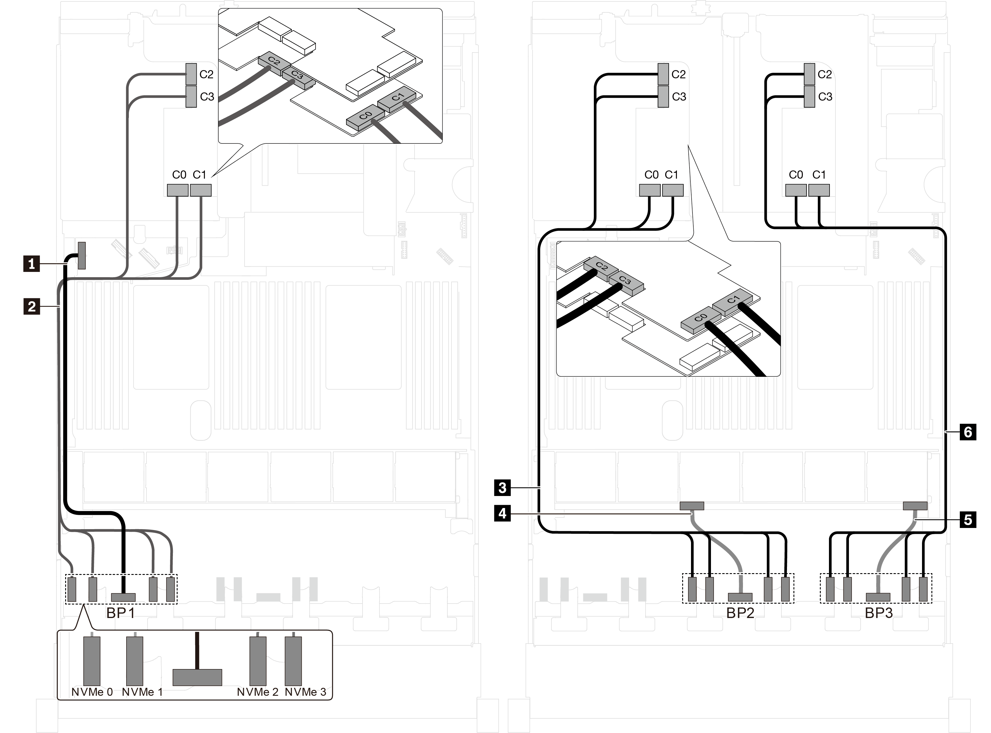
Server model: twenty-four 2.5-inch NVMe drives, three NVMe 1611-8P switch adapters
| Cable | From | To |
|---|---|---|
| 1 Power cable for front backplane 1 | Power connector on front backplane 1 | Backplane power connector 1 on the system board |
| 2 NVMe signal cable for front backplane 1 | NVMe 0, NVMe 1, NVMe 2, and NVMe 3 connectors on front backplane 1 | C0, C1, C2, and C3 connectors on the NVMe 1611-8P switch adapter installed in PCIe slot 6 |
| 3 NVMe signal cable for front backplane 2 | NVMe 0, NVMe 1, NVMe 2, and NVMe 3 connectors on front backplane 2 | C0, C1, C2, and C3 connectors on the NVMe 1611-8P switch adapter installed in PCIe slot 5 |
| 4 Power cable for front backplane 2 | Power connector on front backplane 2 | Backplane power connector 2 on the system board |
| 5 Power cable for front backplane 3 | Power connector on front backplane 3 | Backplane power connector 3 on the system board |
| 6 NVMe signal cable for front backplane 3 | NVMe 0, NVMe 1, NVMe 2, and NVMe 3 connectors on front backplane 3 | C0, C1, C2, and C3 connectors on the NVMe 1611-8P switch adapter installed in PCIe slot 1 |