Server models with sixteen 2.5-inch drives
Use this section to understand the cable routing for server models with sixteen 2.5-inch drives.
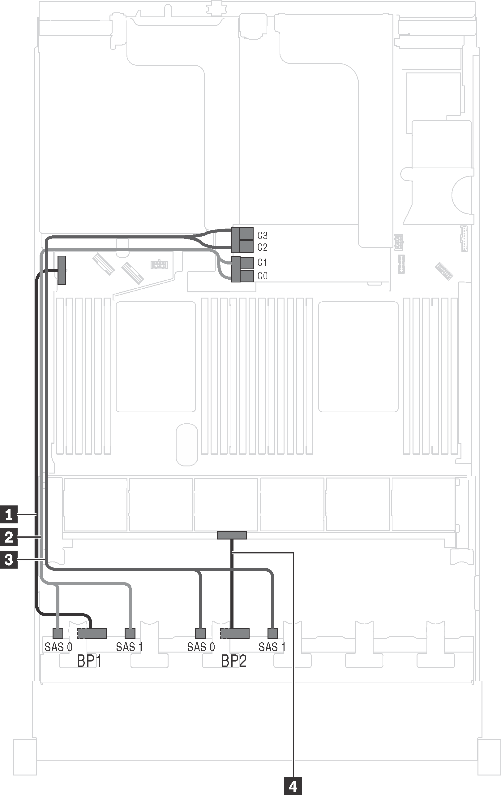
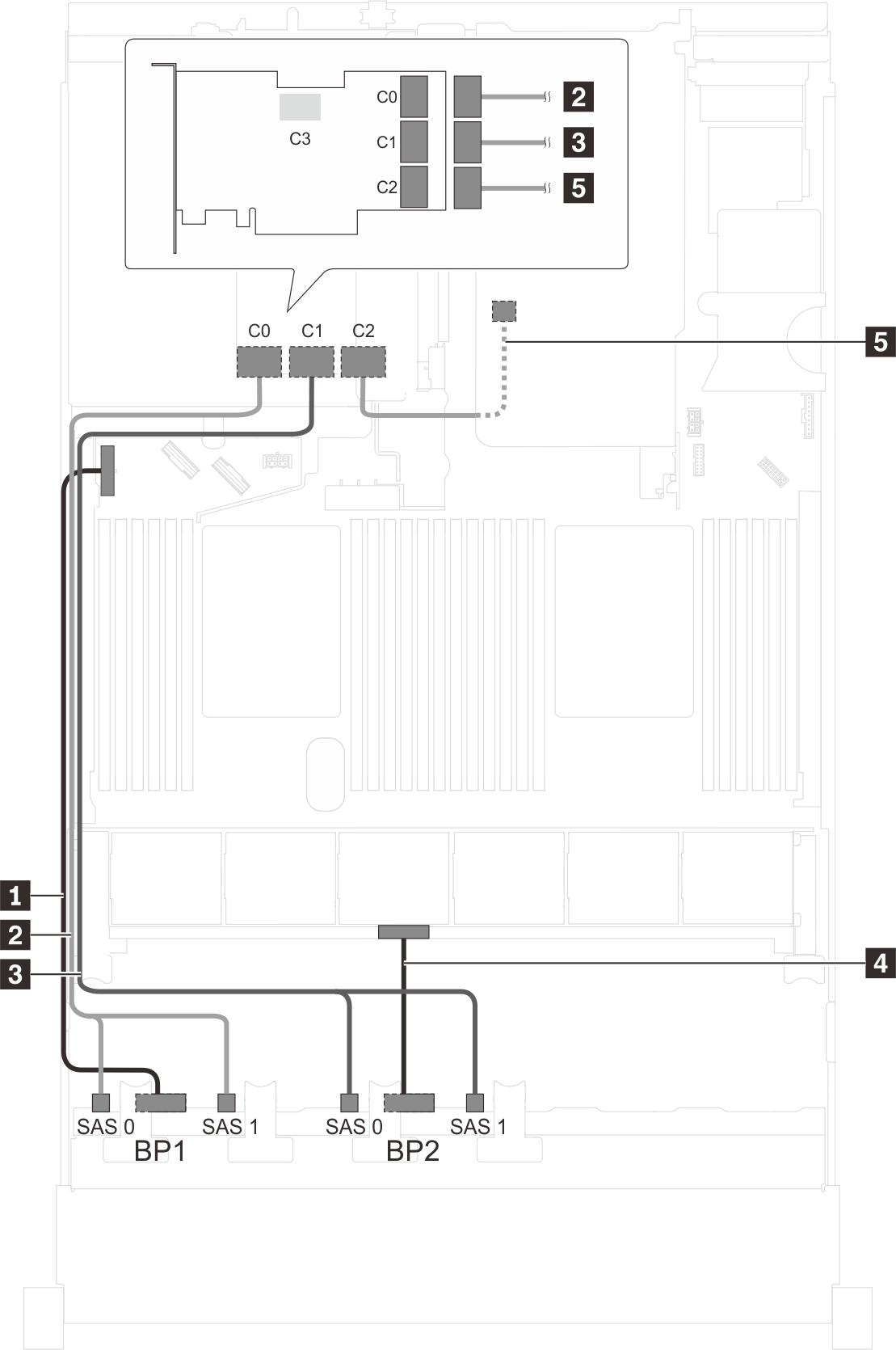
Server model: sixteen 2.5-inch SAS/SATA drives, one 16i HBA/RAID adapter
Gen 4 HBA/RAID adapter cannot be installed in the inner raid adapter slot.
*When Gen 4 HBA/RAID adapter is installed, ensure you use Gen 4 SAS signal cable (ThinkSystem SR550/SR590/SR650 2.5" SAS/SATA/AnyBay 8-Bay X40 RAID Cable Kit).
| Cable | From | To |
|---|---|---|
| 1 Power cable for front backplane 1 | Power connector on front backplane 1 | Backplane power connector 1 on the system board |
| 2 SAS signal cable for front backplane 1* | SAS 0 and SAS 1 connectors on front backplane 1 | 16i HBA/RAID adapter on the RAID adapter slot
|
| 3 SAS signal cable for front backplane 2* | SAS 0 and SAS 1 connectors on front backplane 2 | 16i HBA/RAID adapter on the RAID adapter slot
|
| 4 Power cable for front backplane 2 | Power connector on front backplane 2 | Backplane power connector 2 on the system board |
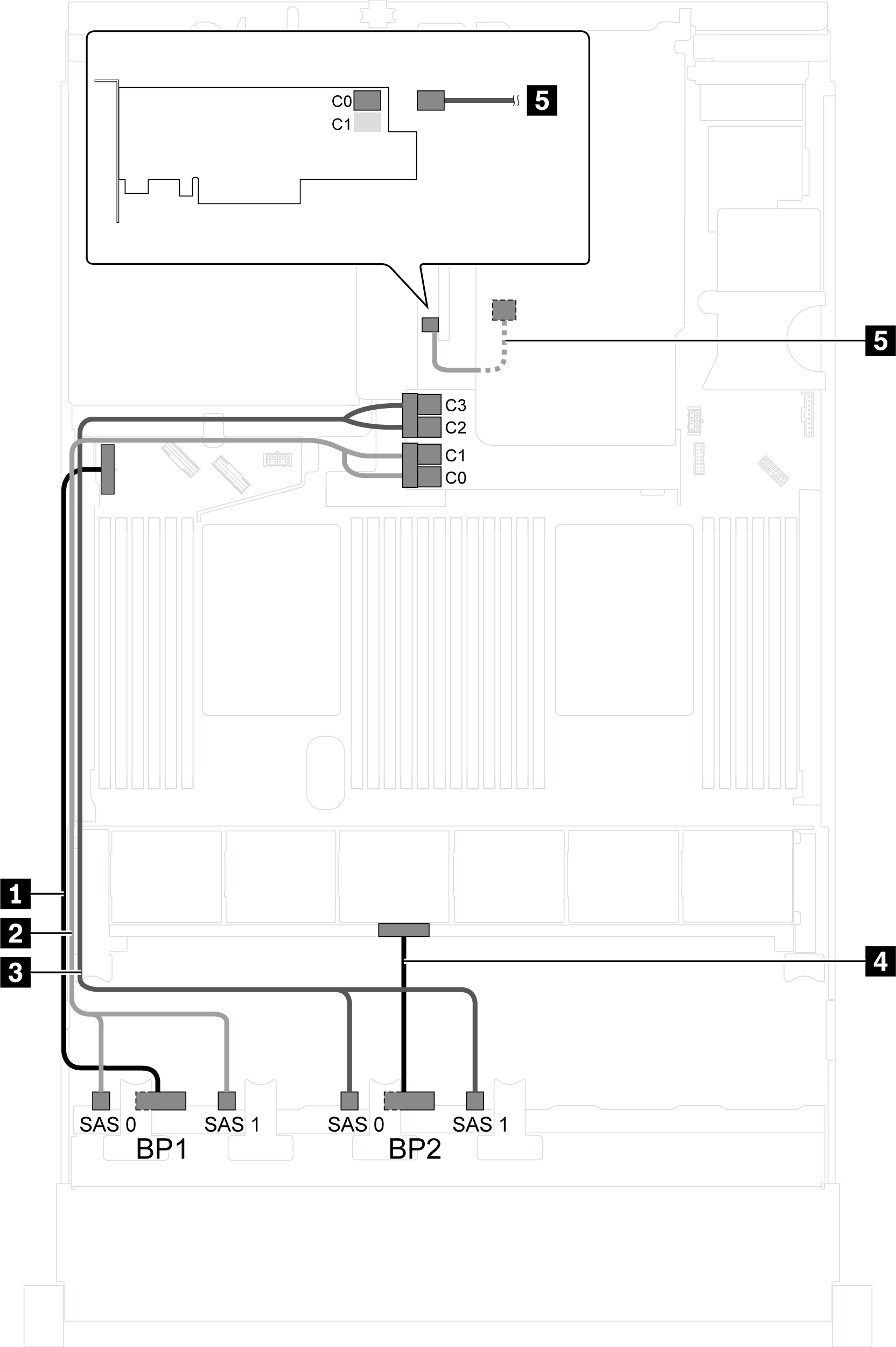
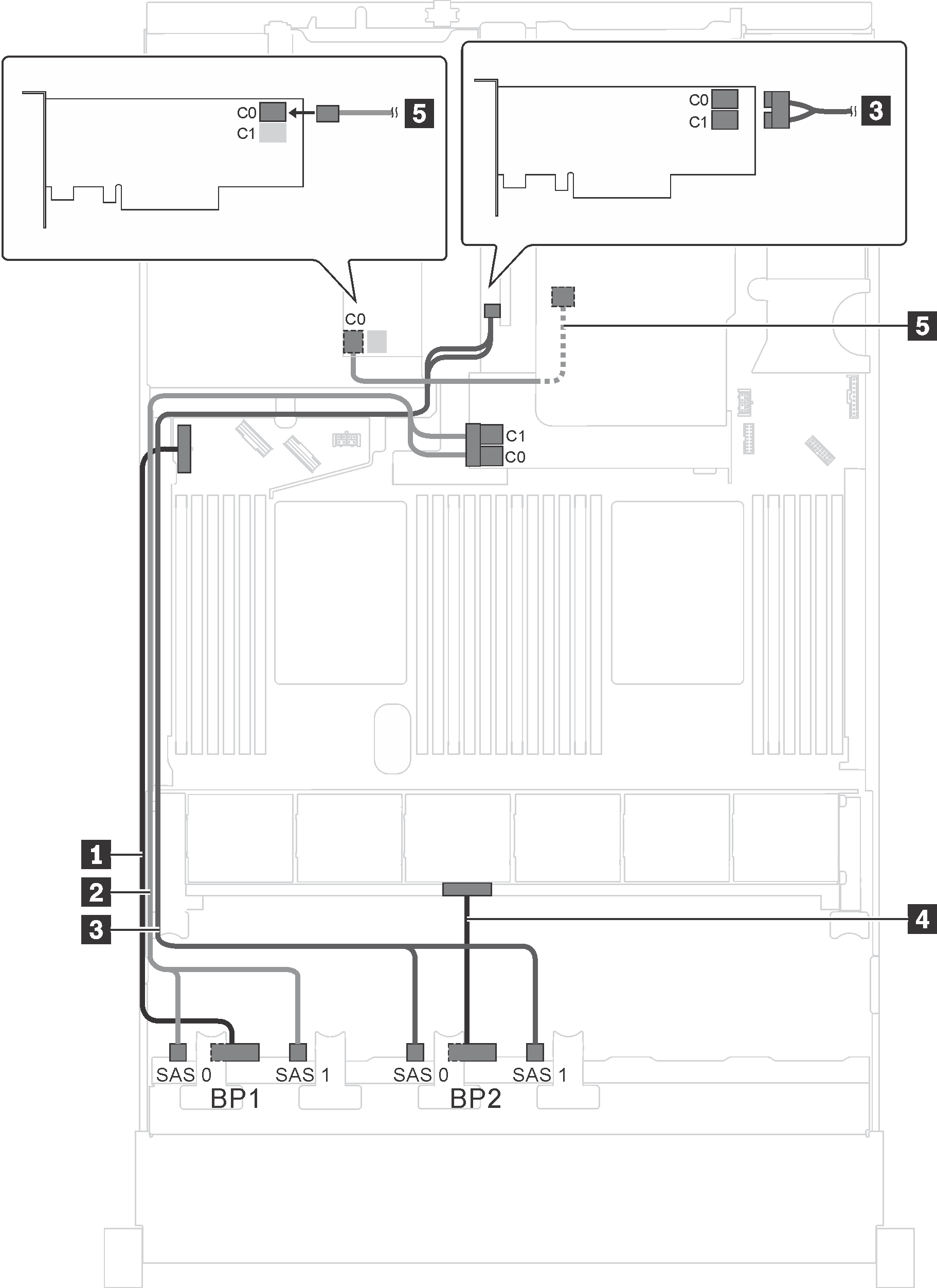
Server model: sixteen 2.5-inch SAS/SATA drives, the rear hot-swap drive assembly, one Gen 3 8i HBA/RAID adapter, one Gen 3 16i HBA/RAID adapter
| Cable | From | To |
|---|---|---|
| 1 Power cable for front backplane 1 | Power connector on front backplane 1 | Backplane power connector 1 on the system board |
| 2 SAS signal cable for front backplane 1 | SAS 0 and SAS 1 connectors on front backplane 1 | C0 and C1 connectors of Gen 3 16i HBA/RAID adapter on the RAID adapter slot |
| 3 SAS signal cable for front backplane 2 | SAS 0 and SAS 1 connectors on front backplane 2 | C2 and C3 connectors of Gen 3 16i HBA/RAID adapter on the RAID adapter slot |
| 4 Power cable for front backplane 2 | Power connector on front backplane 2 | Backplane power connector 2 on the system board |
| 5 SAS signal cable for the rear hot-swap drive assembly | Signal connector on the rear hot-swap drive assembly | C0 connector of 8i HBA/RAID adapter on PCIe slot 4 |
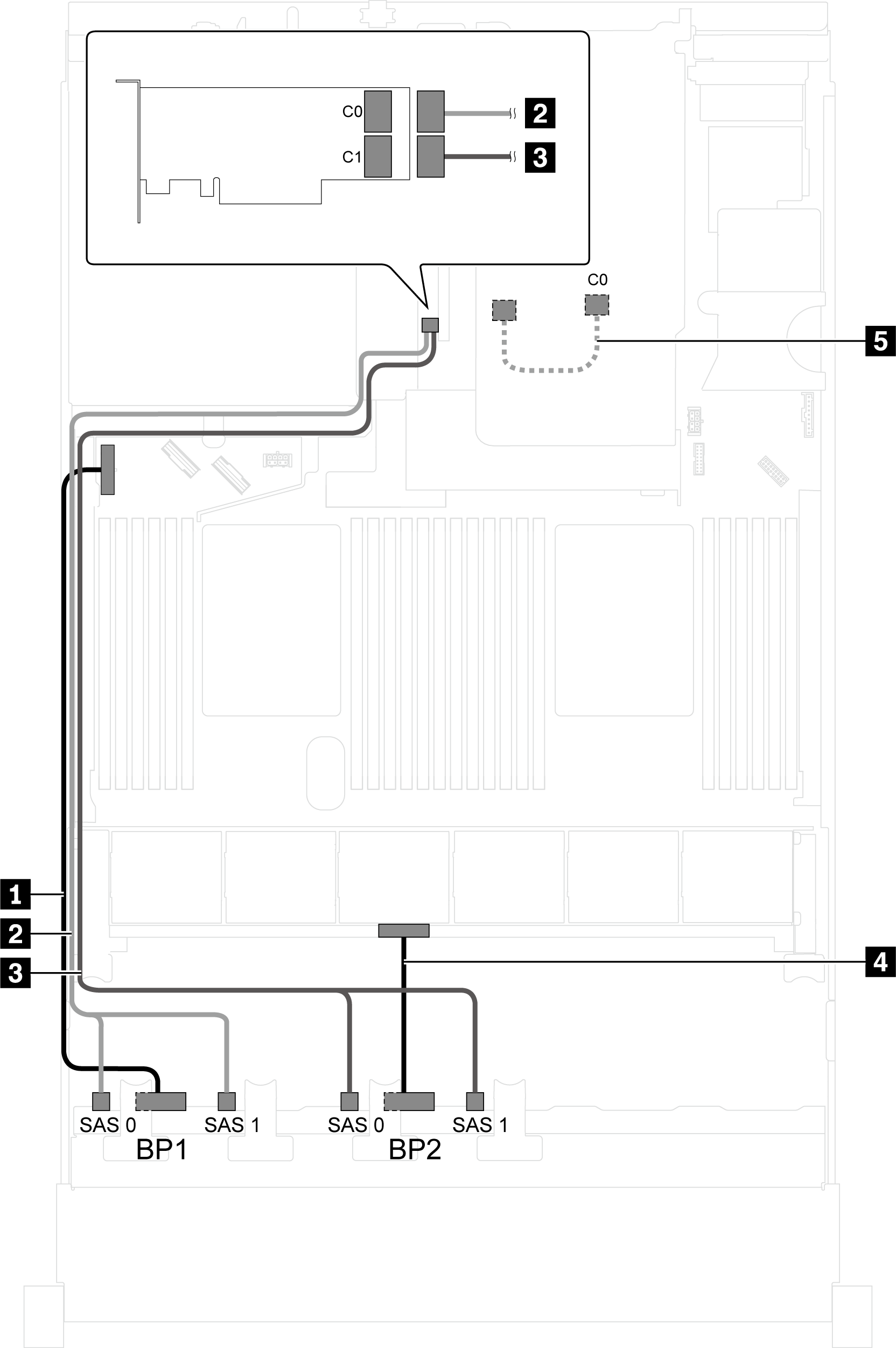
Server model: sixteen 2.5-inch SAS/SATA drives, the rear hot-swap drive assembly, one Gen 4 8i HBA/RAID adapter, one Gen 4 16i HBA/RAID adapter
Cable 2/3: ThinkSystem SR550/SR590/SR650 2.5" SAS/SATA/AnyBay 8-Bay X40 RAID Cable Kit
Cable 5: ThinkSystem SR590/SR650 3.5" SAS/SATA 2-Bay Rear BP X40 RAID Cable Kit
| Cable | From | To |
|---|---|---|
| 1 Power cable for front backplane 1 | Power connector on front backplane 1 | Backplane power connector 1 on the system board |
| 2 SAS signal cable for front backplane 1 | SAS 0 and SAS 1 connectors on front backplane 1 | C0 connector of Gen 4 16i HBA/RAID adapter on PCIe slot 4 |
| 3 SAS signal cable for front backplane 2 | SAS 0 and SAS 1 connectors on front backplane 2 | C1 connector of Gen 4 16i HBA/RAID adapter on PCIe slot 4 |
| 4 Power cable for front backplane 2 | Power connector on front backplane 2 | Backplane power connector 2 on the system board |
| 5 SAS signal cable for the rear hot-swap drive assembly | Signal connector on the rear hot-swap drive assembly | C0 connector of Gen 4 8i HBA/RAID adapter on PCIe slot 2 |
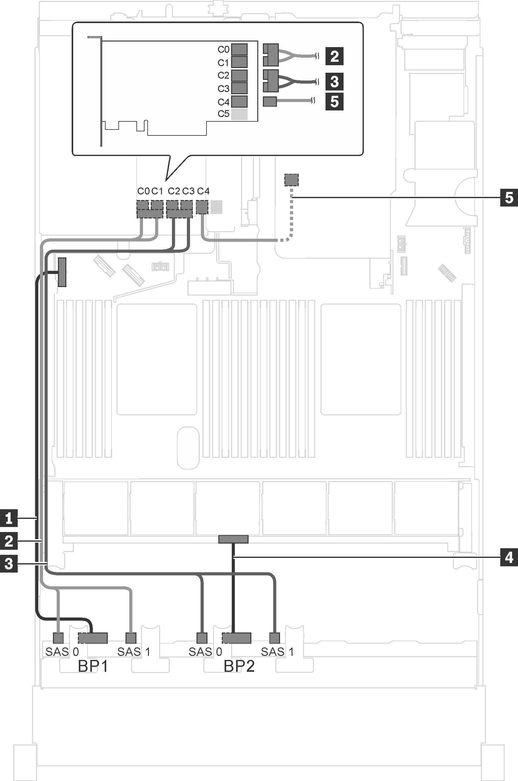
Server model: sixteen 2.5-inch SAS/SATA drives, the rear hot-swap drive assembly, one 24i RAID adapter
| Cable | From | To |
|---|---|---|
| 1 Power cable for front backplane 1 | Power connector on front backplane 1 | Backplane power connector 1 on the system board |
| 2 SAS signal cable for front backplane 1 | SAS 0 and SAS 1 connectors on front backplane 1 | C0 and C1 connectors on the 24i RAID adapter installed in PCIe slot 5 |
| 3 SAS signal cable for front backplane 2 | SAS 0 and SAS 1 connectors on front backplane 2 | C2 and C3 connectors on the 24i RAID adapter installed in PCIe slot 5 |
| 4 Power cable for front backplane 2 | Power connector on front backplane 2 | Backplane power connector 2 on the system board |
| 5 SAS signal cable for the rear hot-swap drive assembly | Signal connector on the rear hot-swap drive assembly | C4 connector on the 24i RAID adapter installed in PCIe slot 5 |
Server model: sixteen 2.5-inch SAS/SATA drives, the rear hot-swap drive assembly, one 32i RAID adapter
The cable routing illustration is based on the scenario that the rear hot-swap drive assembly is installed. Depending on the model, the rear hot-swap drive assembly and the cable 5 might not be available on your server.
Gen 4 HBA/RAID adapter cannot be installed in the inner raid adapter slot.
- *Ensure you use Gen 4 SAS signal cable:
Cable 2/3: ThinkSystem SR550/SR590/SR650 2.5" SAS/SATA/AnyBay 8-Bay X40 RAID Cable Kit
Cable 5: ThinkSystem SR590/SR650 3.5" SAS/SATA 2-Bay Rear BP X40 RAID Cable Kit
| Cable | From | To |
|---|---|---|
| 1 Power cable for front backplane 1 | Power connector on front backplane 1 | Backplane power connector 1 on the system board |
| 2 SAS signal cable for front backplane 1* | SAS 0 and SAS 1 connectors on front backplane 1 | C0 connector on the 32i RAID adapter on PCIe slot 5 |
| 3 SAS signal cable for front backplane 2* | SAS 0 and SAS 1 connectors on front backplane 2 | C1 connector on the 32i RAID adapter on PCIe slot 5 |
| 4 Power cable for front backplane 2 | Power connector on front backplane 2 | Backplane power connector 2 on the system board |
| 5 SAS signal cable for the rear hot-swap drive assembly* | Signal connector on the rear hot-swap drive assembly | C2 connector on the 32i RAID adapter on PCIe slot 5 |
Server model: sixteen 2.5-inch SAS/SATA drives, the rear hot-swap drive assembly, three 8i HBA/RAID adapters
The cable routing illustration is based on the scenario that the rear hot-swap drive assembly is installed. Depending on the model, the rear hot-swap drive assembly and the 8i HBA/RAID adapter in PCIe slot 5 might not be available on your server.
Gen 4 HBA/RAID adapter cannot be installed in the inner raid adapter slot.
- *When Gen 4 HBA/RAID adapter is installed, ensure you use Gen 4 SAS signal cable:
Cable 2/3: ThinkSystem SR550/SR590/SR650 2.5" SAS/SATA/AnyBay 8-Bay X40 RAID Cable Kit
Cable 5: ThinkSystem SR590/SR650 3.5" SAS/SATA 2-Bay Rear BP X40 RAID Cable Kit
| Cable | From | To |
|---|---|---|
| 1 Power cable for front backplane 1 | Power connector on front backplane 1 | Backplane power connector 1 on the system board |
| 2 SAS signal cable for front backplane 1* | SAS 0 and SAS 1 connectors on front backplane 1 | 8i HBA/RAID adapter on the RAID adapter slot
|
| 3 SAS signal cable for front backplane 2* | SAS 0 and SAS 1 connectors on front backplane 2 | 8i HBA/RAID adapter on PCIe slot 4
|
| 4 Power cable for front backplane 2 | Power connector on front backplane 2 | Backplane power connector 2 on the system board |
| 5 SAS signal cable for the rear hot-swap drive assembly* | Signal connector on the rear hot-swap drive assembly | 8i HBA/RAID adapter installed in PCIe slot 5
|
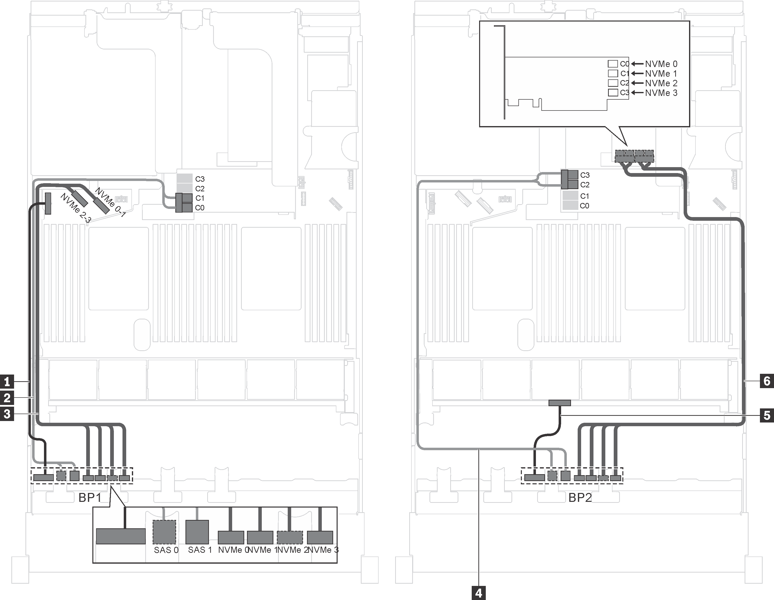
Server model: twelve 2.5-inch SAS/SATA drives, four 2.5-inch SAS/SATA/NVMe drives, one 16i HBA/RAID adapter
Gen 4 HBA/RAID adapter cannot be installed in the inner raid adapter slot.
*When Gen 4 HBA/RAID adapter is installed, ensure you use Gen 4 SAS signal cable (ThinkSystem SR550/SR590/SR650 2.5" SAS/SATA/AnyBay 8-Bay X40 RAID Cable Kit).
| Cable | From | To |
|---|---|---|
| 1 Power cable for front backplane 1 | Power connector on backplane 1 | Backplane power connector 1 on the system board |
| 2 SAS signal cable for front backplane 1* | SAS 0 and SAS 1 connectors on backplane 1 | 16i HBA/RAID adapter on the RAID adapter slot
|
| 3 NVMe signal cable for front backplane 1 | NVMe 0, NVMe 1, NVMe 2, and NVMe 3 connectors on front backplane 1 | NVMe 0–1 and NVMe 2–3 connectors on the system board |
| 4 SAS signal cable for front backplane 2* | SAS 0 and SAS 1 connectors on front backplane 2 | 16i HBA/RAID adapter on the RAID adapter slot
|
| 5 Power cable for front backplane 2 | Power connector on front backplane 2 | Backplane power connector 2 on the system board |
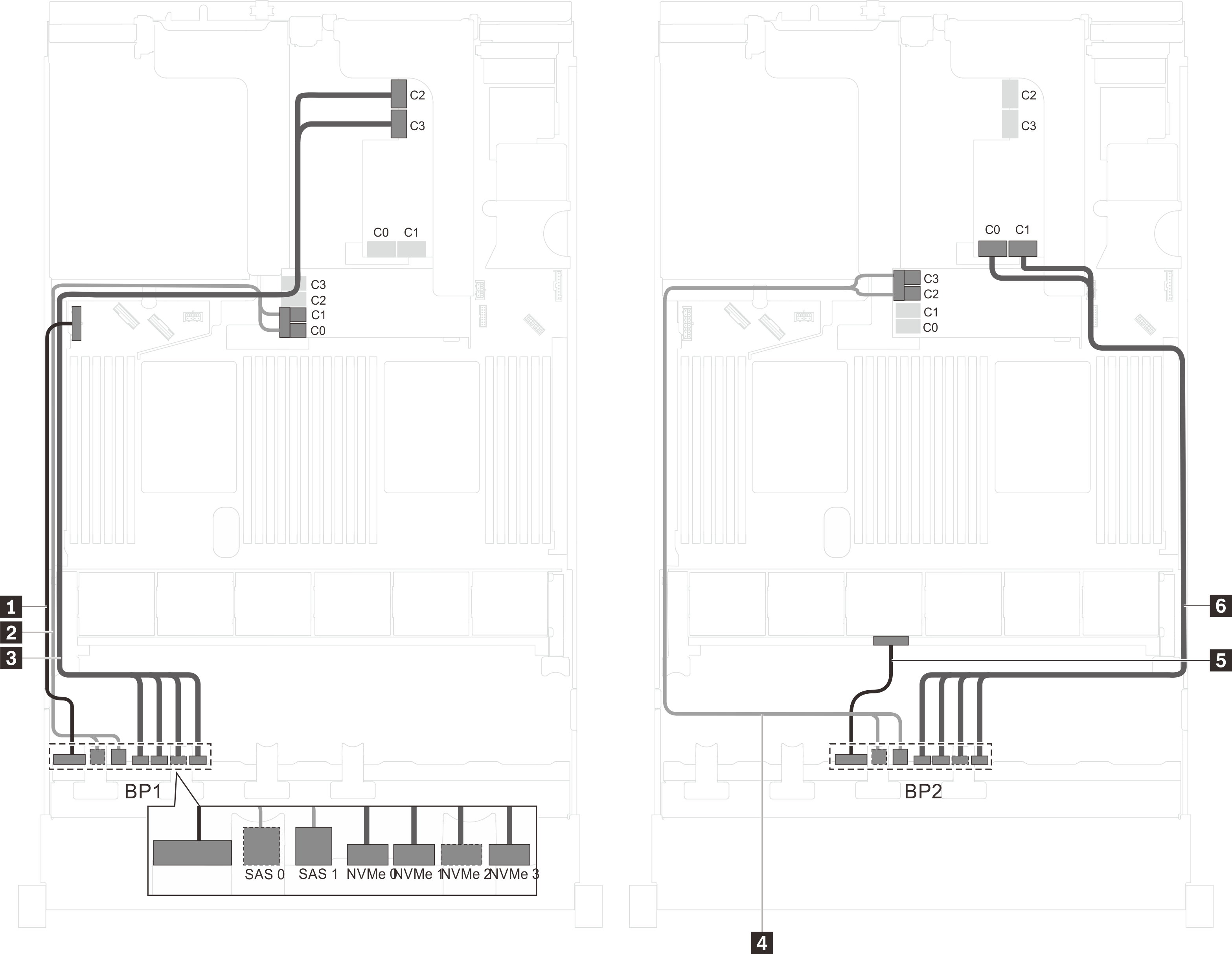
Server model: twelve 2.5-inch SAS/SATA drives, four 2.5-inch SAS/SATA/NVMe drives, one 24i RAID adapter
| Cable | From | To |
|---|---|---|
| 1 Power cable for front backplane 1 | Power connector on backplane 1 | Backplane power connector 1 on the system board |
| 2 SAS signal cable for front backplane 1 | SAS 0 and SAS 1 connectors on backplane 1 | C0 and C1 connectors on the 24i RAID adapter on the riser assembly |
| 3 NVMe signal cable for front backplane 1 | NVMe 0, NVMe 1, NVMe 2, and NVMe 3 connectors on front backplane 1 | NVMe 0–1 and NVMe 2–3 connectors on the system board |
| 4 SAS signal cable for front backplane 2 | SAS 0 and SAS 1 connectors on front backplane 2 | C2 and C3 connectors on the 24i RAID adapter on the riser assembly |
| 5 Power cable for front backplane 2 | Power connector on front backplane 2 | Backplane power connector 2 on the system board |
Server model: twelve 2.5-inch SAS/SATA drives, four 2.5-inch SAS/SATA/NVMe drives, one 32i RAID adapter
The 32i RAID adapter can be installed in riser assembly 1 or riser assembly 2.
Gen 4 HBA/RAID adapter cannot be installed in the inner raid adapter slot.
*Ensure you use Gen 4 SAS signal cable (ThinkSystem SR550/SR590/SR650 2.5" SAS/SATA/AnyBay 8-Bay X40 RAID Cable Kit).
| Cable | From | To |
|---|---|---|
| 1 Power cable for front backplane 1 | Power connector on backplane 1 | Backplane power connector 1 on the system board |
| 2 SAS signal cable for front backplane 1* | SAS 0 and SAS 1 connectors on backplane 1 | C0 connector on the 32i RAID adapter on the riser assembly |
| 3 NVMe signal cable for front backplane 1 | NVMe 0, NVMe 1, NVMe 2, and NVMe 3 connectors on front backplane 1 | NVMe 0–1 and NVMe 2–3 connectors on the system board |
| 4 SAS signal cable for front backplane 2* | SAS 0 and SAS 1 connectors on front backplane 2 | C1 connector on the 32i RAID adapter on the riser assembly |
| 5 Power cable for front backplane 2 | Power connector on front backplane 2 | Backplane power connector 2 on the system board |
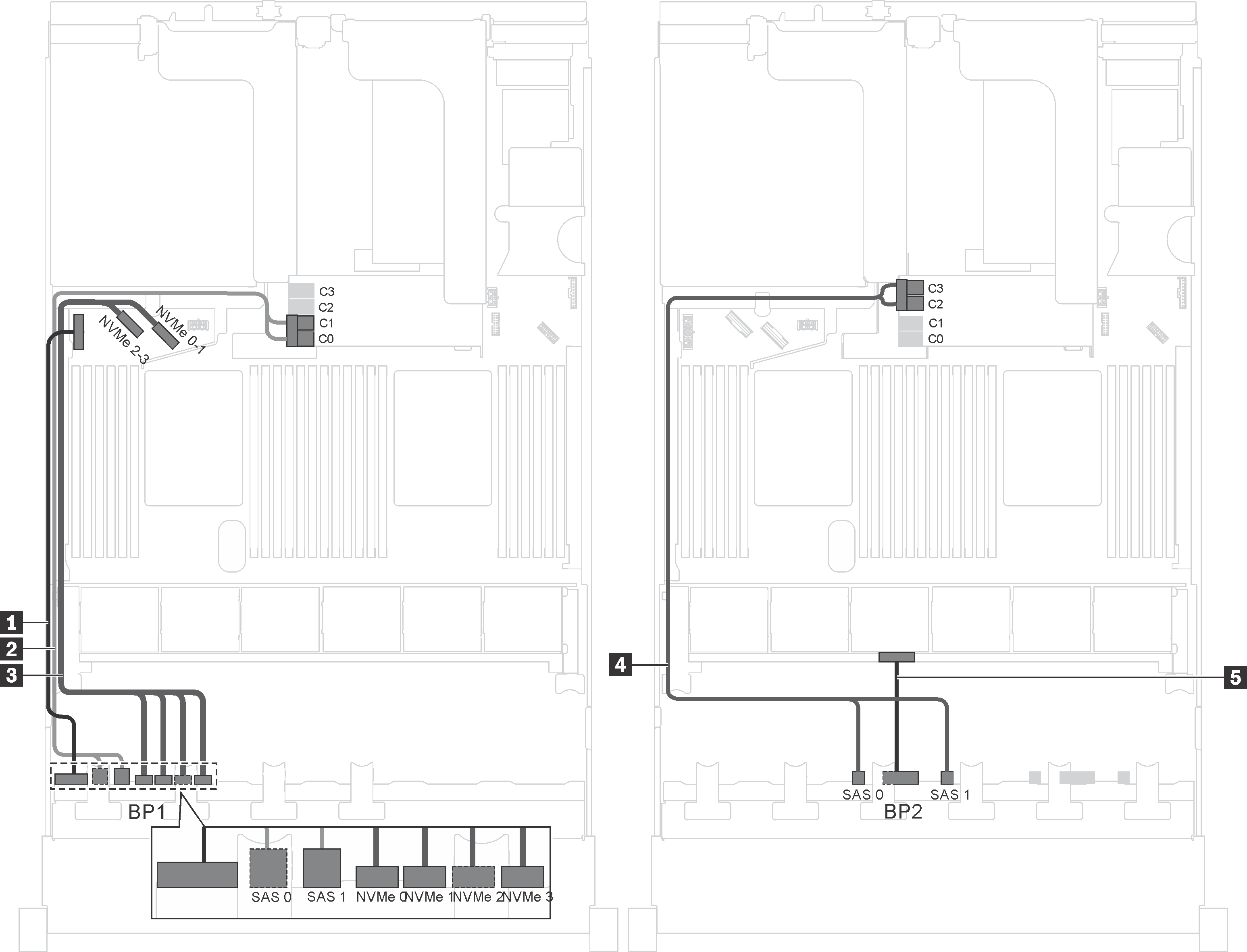
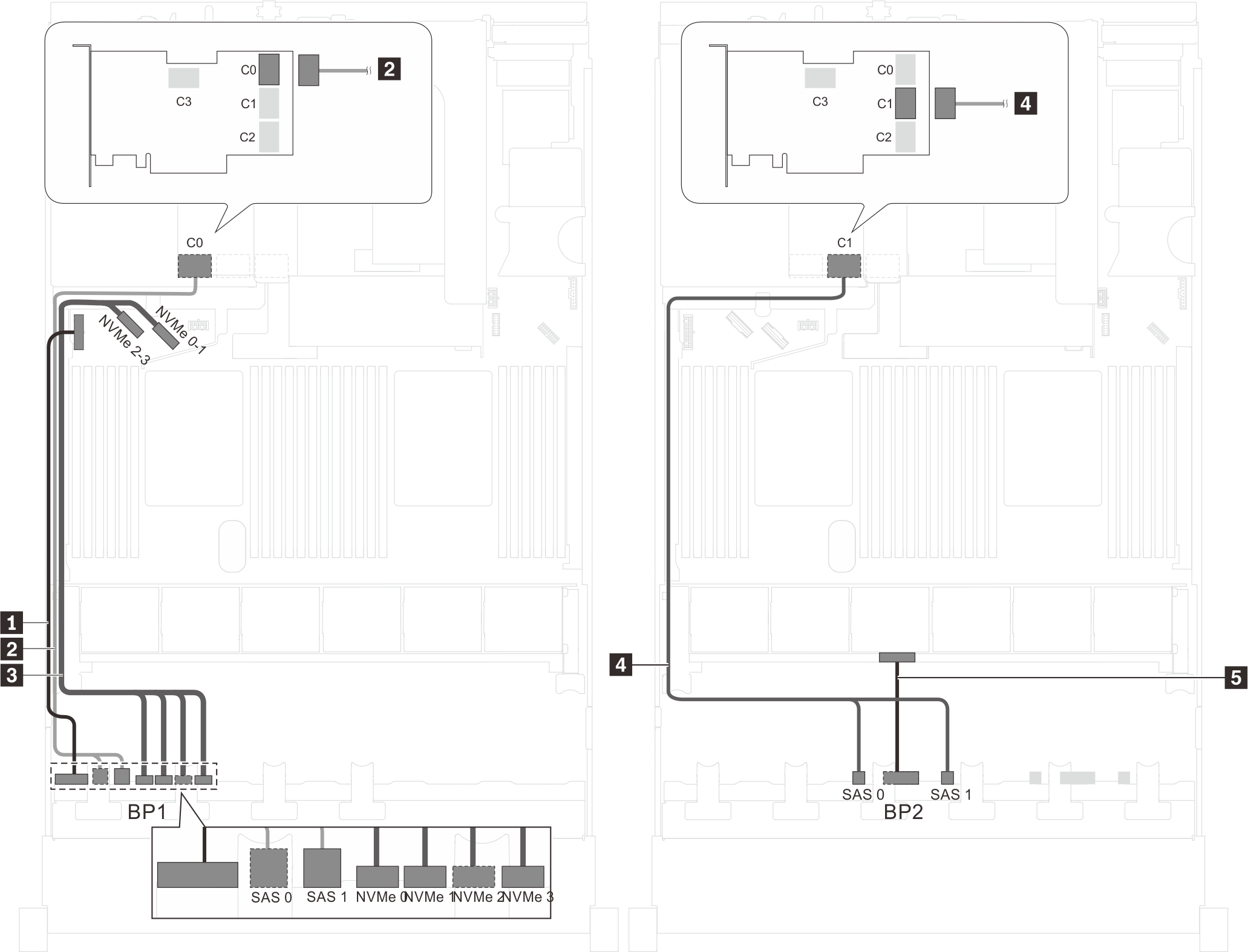
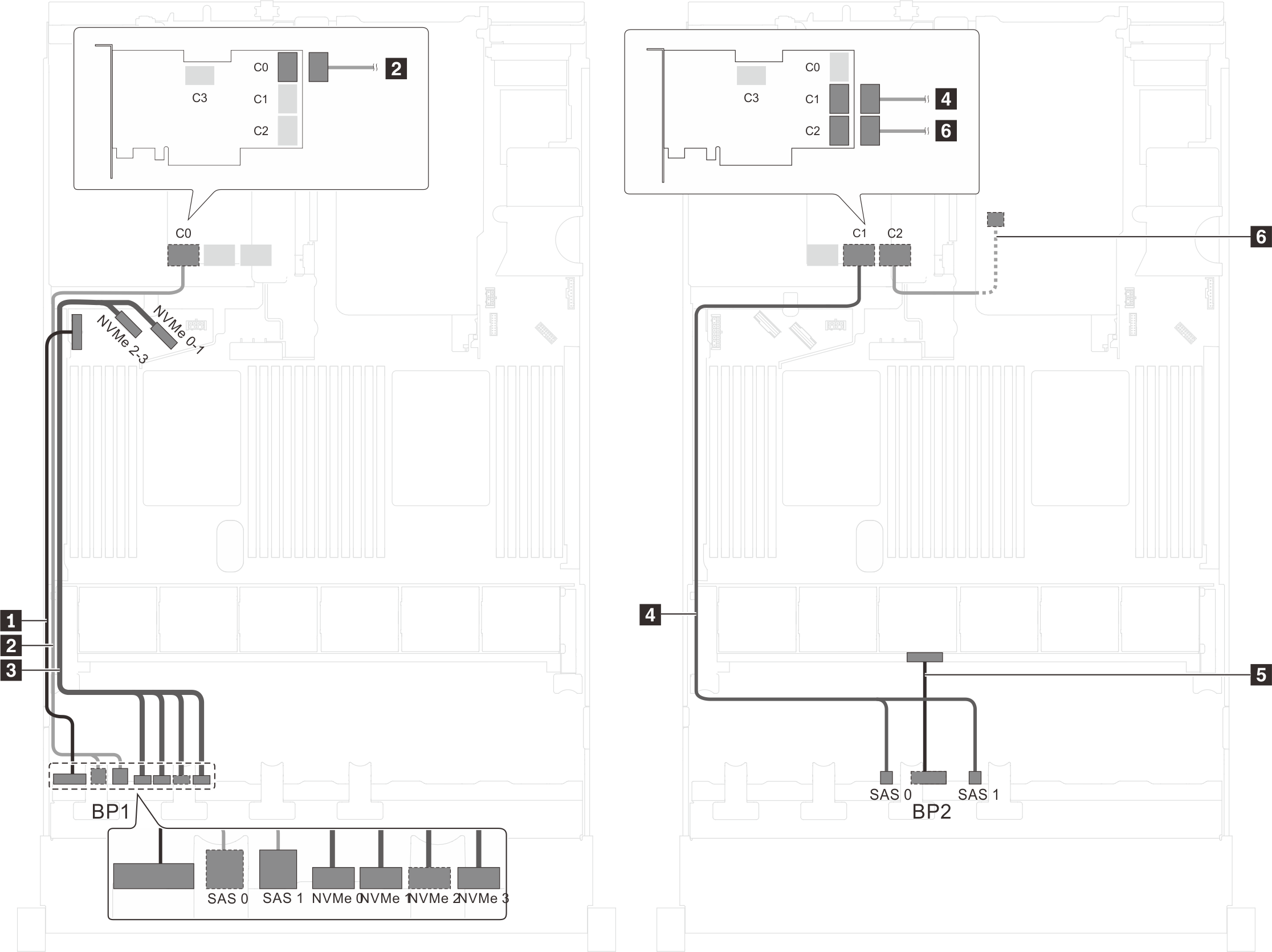
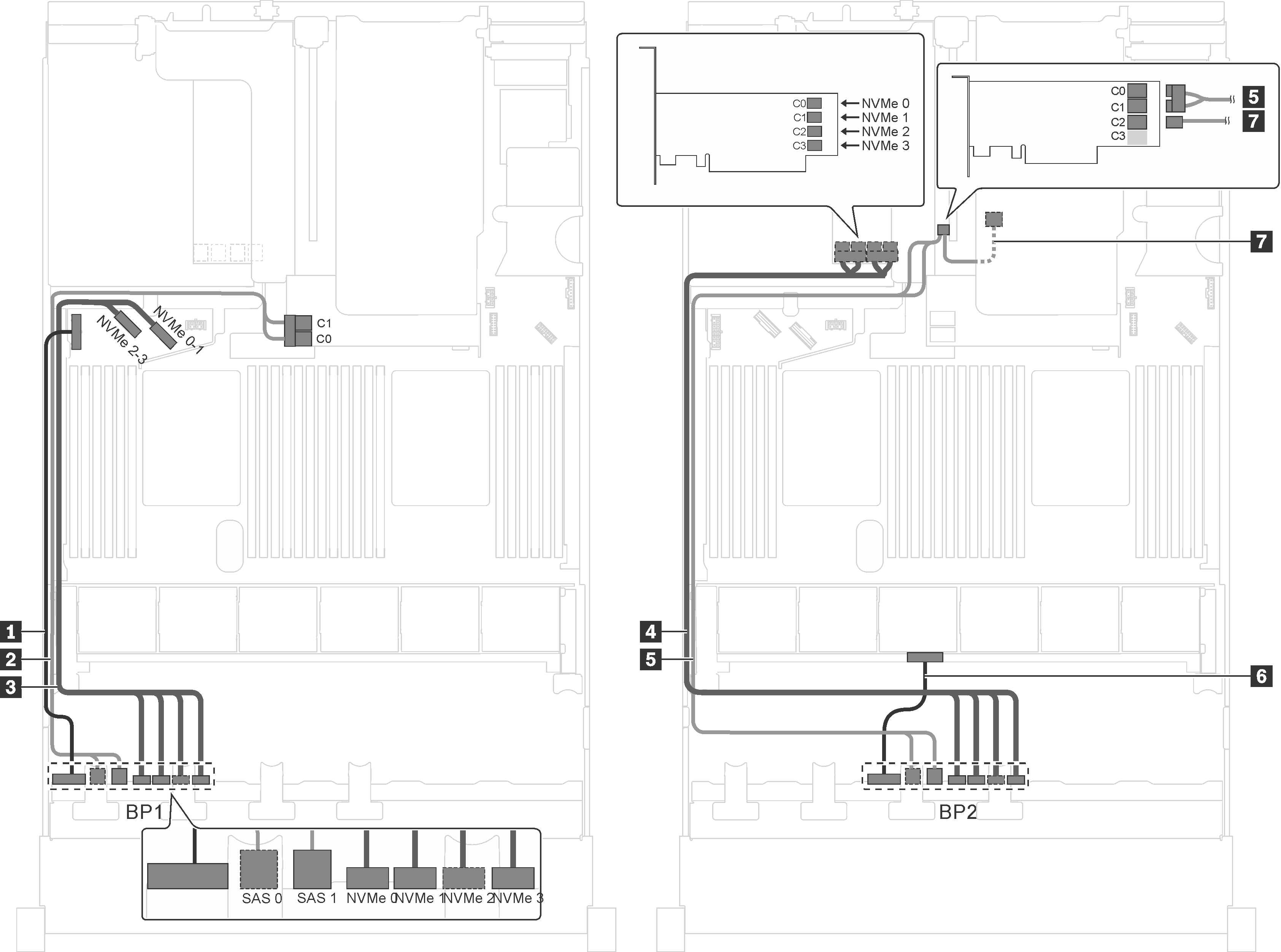
Server model: twelve 2.5-inch SAS/SATA drives, four 2.5-inch SAS/SATA/NVMe drives, the rear hot-swap drive assembly, one 8i HBA/RAID adapter, one 16i HBA/RAID adapter
Gen 4 HBA/RAID adapter cannot be installed in the inner raid adapter slot.
- *When Gen 4 HBA/RAID adapter is installed, ensure you use Gen 4 SAS signal cable:
Cable 2/4: ThinkSystem SR550/SR590/SR650 2.5" SAS/SATA/AnyBay 8-Bay X40 RAID Cable Kit
Cable 6: ThinkSystem SR590/SR650 3.5" SAS/SATA 2-Bay Rear BP X40 RAID Cable Kit
| Cable | From | To |
|---|---|---|
| 1 Power cable for front backplane 1 | Power connector on front backplane 1 | Backplane power connector 1 on the system board |
| 2 SAS signal cable for front backplane 1* | SAS 0 and SAS 1 connectors on front backplane 1 | 8i HBA/RAID adapter on the RAID adapter slot
|
| 3 NVMe signal cable for front backplane 1 | NVMe 0, NVMe 1, NVMe 2, and NVMe 3 connectors on front backplane 1 | NVMe 0–1 and NVMe 2–3 connectors on the system board |
| 4 SAS signal cable for front backplane 2* | SAS 0 and SAS 1 connectors on front backplane 2 | 16i HBA/RAID adapter on PCIe slot 4
|
| 5 Power cable for front backplane 2 | Power connector on front backplane 2 | Backplane power connector 2 on the system board |
| 6 SAS signal cable for the rear hot-swap drive assembly* | Signal connector on the rear hot-swap drive assembly | 16i HBA/RAID adapter on PCIe slot 4
|
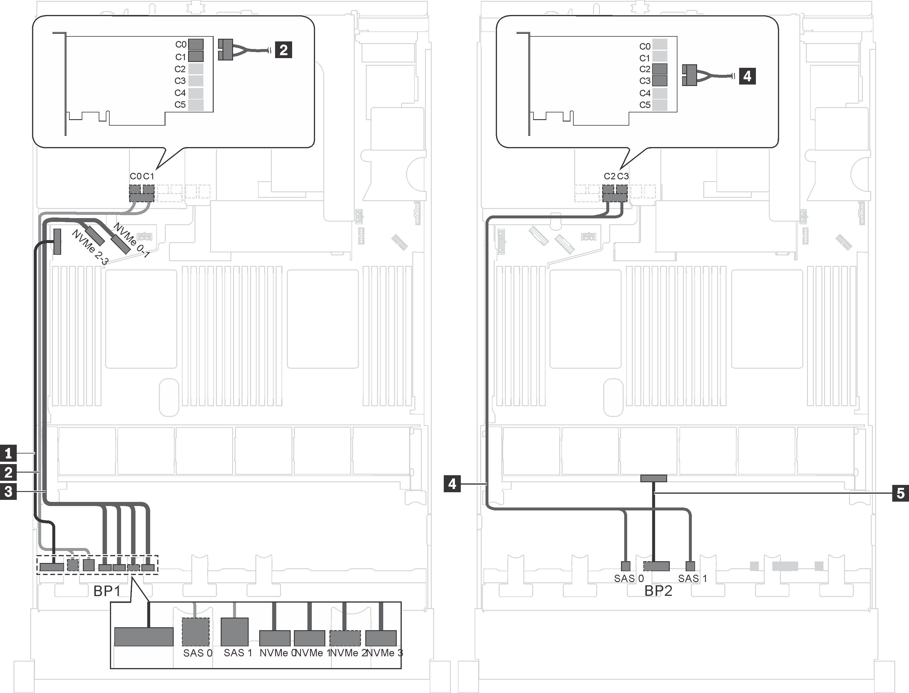
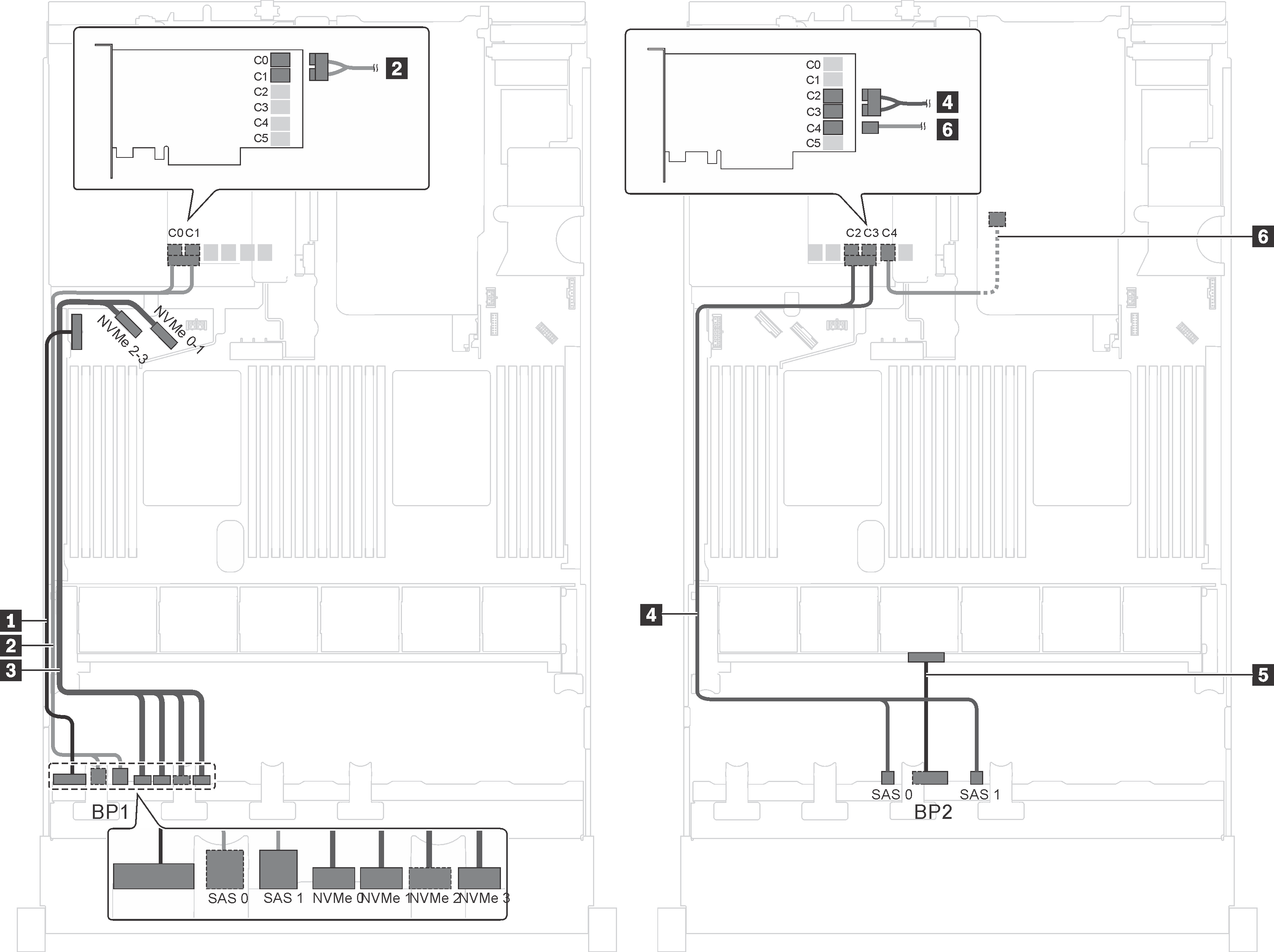
Server model: twelve 2.5-inch SAS/SATA drives, four 2.5-inch SAS/SATA/NVMe drives, the rear hot-swap drive assembly, one 24i RAID adapter
| Cable | From | To |
|---|---|---|
| 1 Power cable for front backplane 1 | Power connector on front backplane 1 | Backplane power connector 1 on the system board |
| 2 SAS signal cable for front backplane 1 | SAS 0 and SAS 1 connectors on front backplane 1 | C0 and C1 connectors on the 24i RAID adapter installed in PCIe slot 5 |
| 3 NVMe signal cable for front backplane 1 | NVMe 0, NVMe 1, NVMe 2, and NVMe 3 connectors on front backplane 1 | NVMe 0–1 and NVMe 2–3 connectors on the system board |
| 4 SAS signal cable for front backplane 2 | SAS 0 and SAS 1 connectors on front backplane 2 | C2 and C3 connectors on the 24i RAID adapter installed in PCIe slot 5 |
| 5 Power cable for front backplane 2 | Power connector on front backplane 2 | Backplane power connector 2 on the system board |
| 6 SAS signal cable for the rear hot-swap drive assembly | Signal connector on the rear hot-swap drive assembly | C4 connector on the 24i RAID adapter installed in PCIe slot 5 |
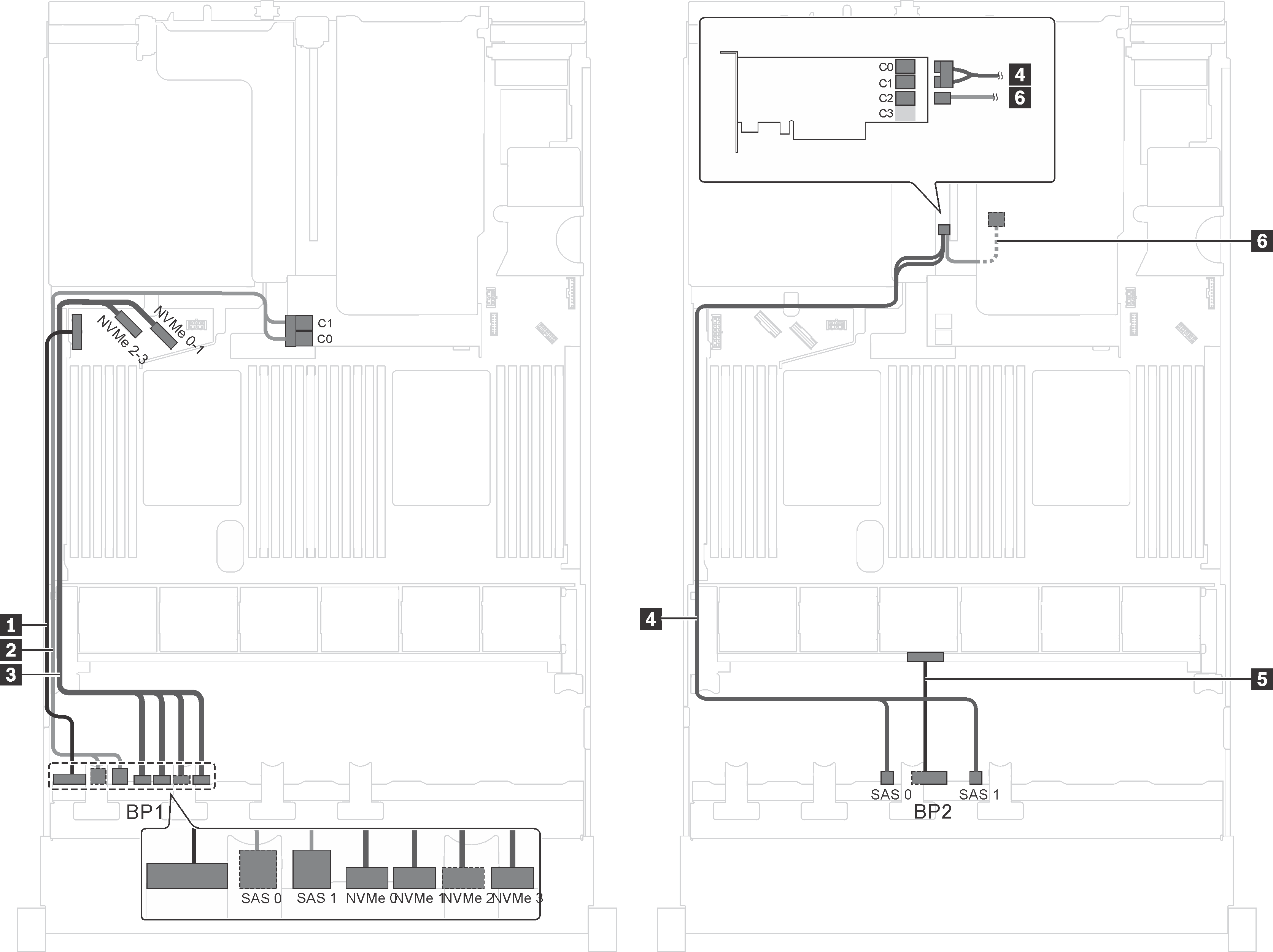
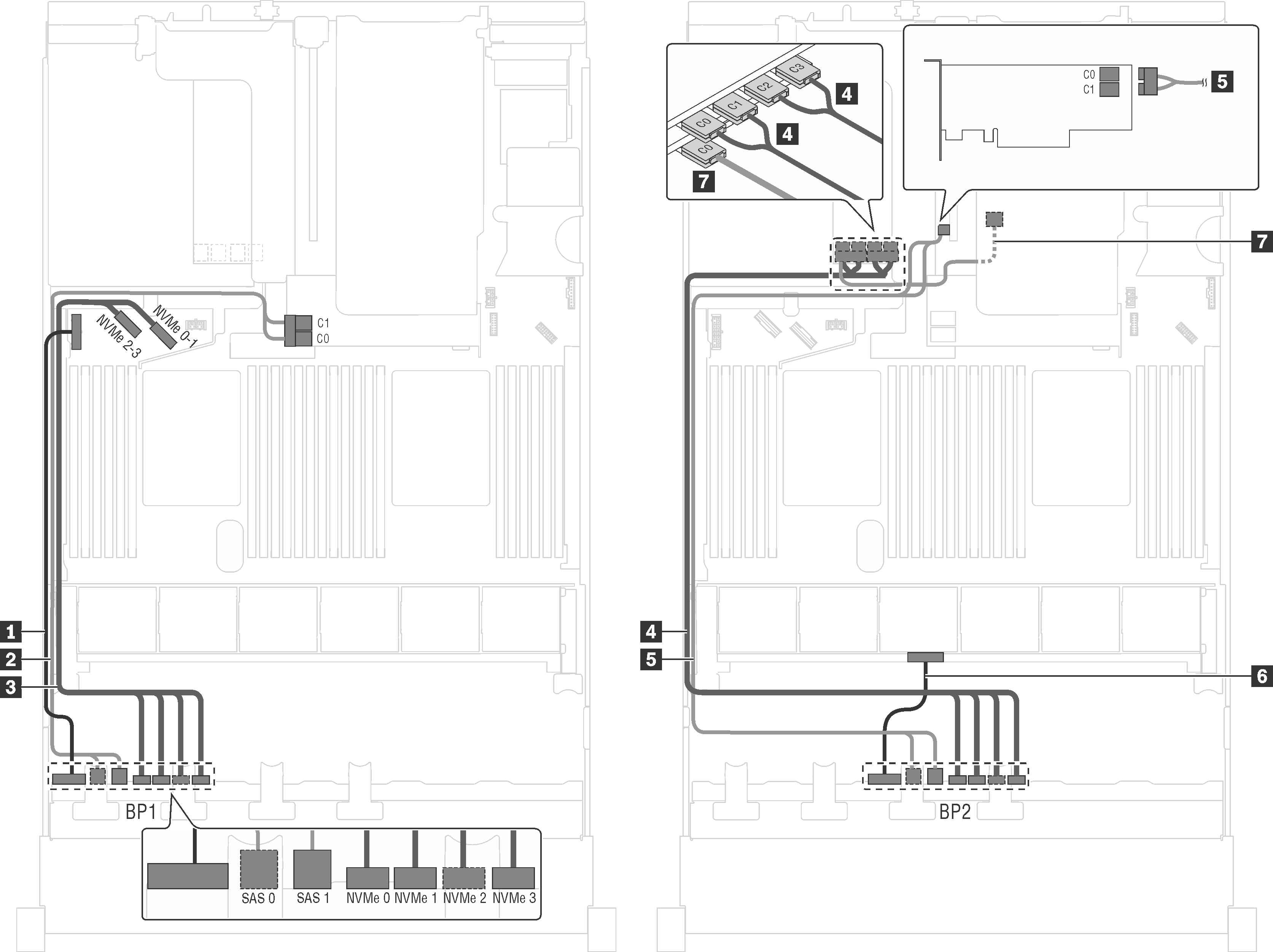
Server model: twelve 2.5-inch SAS/SATA drives, four 2.5-inch SAS/SATA/NVMe drives, the rear hot-swap drive assembly, one 32i RAID adapter
Gen 4 HBA/RAID adapter cannot be installed in the inner raid adapter slot.
- *Ensure you use Gen 4 SAS signal cable:
Cable 2/4: ThinkSystem SR550/SR590/SR650 2.5" SAS/SATA/AnyBay 8-Bay X40 RAID Cable Kit
Cable 6: ThinkSystem SR590/SR650 3.5" SAS/SATA 2-Bay Rear BP X40 RAID Cable Kit
| Cable | From | To |
|---|---|---|
| 1 Power cable for front backplane 1 | Power connector on front backplane 1 | Backplane power connector 1 on the system board |
| 2 SAS signal cable for front backplane 1* | SAS 0 and SAS 1 connectors on front backplane 1 | C0 connector on the 32i RAID adapter on PCIe slot 5 |
| 3 NVMe signal cable for front backplane 1 | NVMe 0, NVMe 1, NVMe 2, and NVMe 3 connectors on front backplane 1 | NVMe 0–1 and NVMe 2–3 connectors on the system board |
| 4 SAS signal cable for front backplane 2* | SAS 0 and SAS 1 connectors on front backplane 2 | C1 connector on the 32i RAID adapter on PCIe slot 5 |
| 5 Power cable for front backplane 2 | Power connector on front backplane 2 | Backplane power connector 2 on the system board |
| 6 SAS signal cable for the rear hot-swap drive assembly* | Signal connector on the rear hot-swap drive assembly | C2 connector on the 32i RAID adapter on PCIe slot 5 |
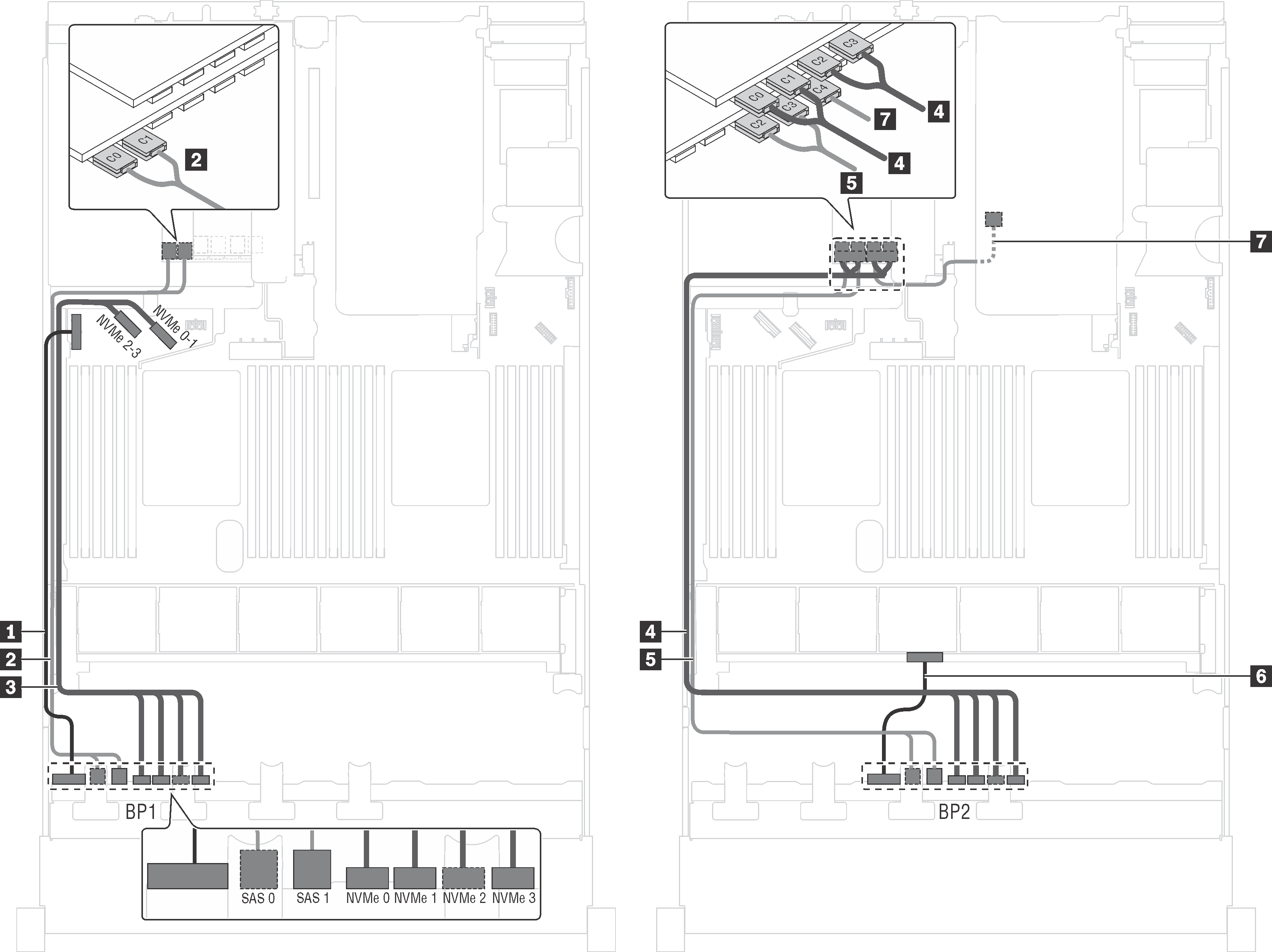
Server model: eight 2.5-inch SAS/SATA drives, eight 2.5-inch SAS/SATA/NVMe drives, one 16i HBA/RAID adapter, one NVMe switch adapter
The cable routing illustration is based on the scenario that the NVMe switch adapter is installed in PCIe slot 1. If the NVMe switch adapter is installed in PCIe slot 5 or PCIe slot 6, route the NVMe signal cable for front backplane 2 along the left side of the chassis.
Gen 4 HBA/RAID adapter cannot be installed in the inner raid adapter slot.
*When Gen 4 HBA/RAID adapter is installed, ensure you use Gen 4 SAS signal cable (ThinkSystem SR550/SR590/SR650 2.5" SAS/SATA/AnyBay 8-Bay X40 RAID Cable Kit).
| Cable | From | To |
|---|---|---|
| 1 Power cable for front backplane 1 | Power connector on front backplane 1 | Backplane power connector 1 on the system board |
| 2 SAS signal cable for front backplane 1* | SAS 0 and SAS 1 connectors on front backplane 1 | 16i HBA/RAID adapter on the RAID adapter slot
|
| 3 NVMe signal cable for front backplane 1 | NVMe 0, NVMe 1, NVMe 2, and NVMe 3 connectors on backplane 1 | NVMe 0–1 and NVMe 2–3 connectors on the system board |
| 4 SAS signal cable for front backplane 2* | SAS 0 and SAS 1 connectors on front backplane 2 | 16i HBA/RAID adapter on the RAID adapter slot
|
| 5 Power cable for front backplane 2 | Power connector on front backplane 2 | Backplane power connector 2 on the system board |
| 6 NVMe signal cable for front backplane 2 | NVMe 0, NVMe 1, NVMe 2, and NVMe 3 connectors on front backplane 2 | C0, C1, C2, and C3 connectors on the NVMe switch adapter installed in PCIe slot 1 |
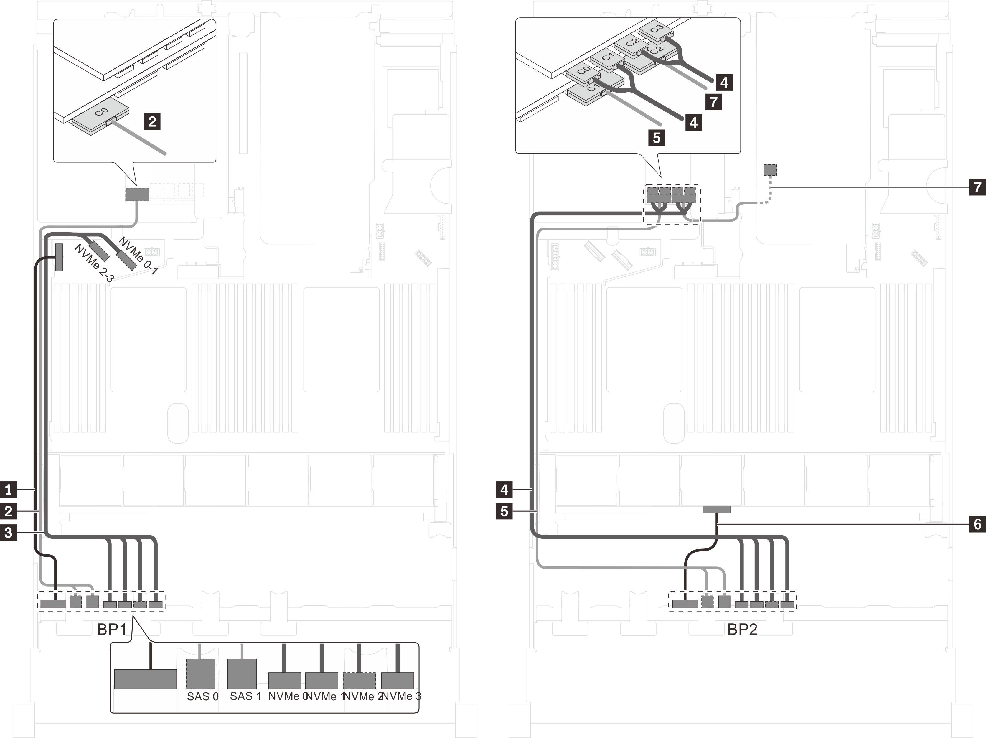
Server model: eight 2.5-inch SAS/SATA drives, eight 2.5-inch SAS/SATA/NVMe drives, one 16i HBA/RAID adapter, one NVMe 1611–8P switch adapter
Gen 4 HBA/RAID adapter cannot be installed in the inner raid adapter slot.
*When Gen 4 HBA/RAID adapter is installed, ensure you use Gen 4 SAS signal cable (ThinkSystem SR550/SR590/SR650 2.5" SAS/SATA/AnyBay 8-Bay X40 RAID Cable Kit).
| Cable | From | To |
|---|---|---|
| 1 Power cable for front backplane 1 | Power connector on front backplane 1 | Backplane power connector 1 on the system board |
| 2 SAS signal cable for front backplane 1* | SAS 0 and SAS 1 connectors on front backplane 1 | 16i HBA/RAID adapter on the RAID adapter slot
|
| 3 NVMe signal cable for front backplane 1 | NVMe 0, NVMe 1, NVMe 2, and NVMe 3 connectors on backplane 1 | C2 and C3 connectors on the NVMe 1611–8P switch adapter installed in PCIe slot 1 |
| 4 SAS signal cable for front backplane 2* | SAS 0 and SAS 1 connectors on front backplane 2 | 16i HBA/RAID adapter on the RAID adapter slot
|
| 5 Power cable for front backplane 2 | Power connector on front backplane 2 | Backplane power connector 2 on the system board |
| 6 NVMe signal cable for front backplane 2 | NVMe 0, NVMe 1, NVMe 2, and NVMe 3 connectors on front backplane 2 | C0 and C1 connectors on the NVMe 1611–8P switch adapter installed in PCIe slot 1 |
Server model: eight 2.5-inch SAS/SATA drives, eight 2.5-inch SAS/SATA/NVMe drives, the rear hot-swap drive assembly, one 8i HBA/RAID adapter, one 16i HBA/RAID adapter, one NVMe switch adapter
Gen 4 HBA/RAID adapter cannot be installed in the inner raid adapter slot.
- *When Gen 4 HBA/RAID adapter is installed, ensure you use Gen 4 SAS signal cable (ThinkSystem SR550/SR590/SR650 2.5" SAS/SATA/AnyBay 8-Bay X40 RAID Cable Kit).
Cable 2/5: ThinkSystem SR550/SR590/SR650 2.5" SAS/SATA/AnyBay 8-Bay X40 RAID Cable Kit
Cable 7: ThinkSystem SR590/SR650 3.5" SAS/SATA 2-Bay Rear BP X40 RAID Cable Kit
| Cable | From | To |
|---|---|---|
| 1 Power cable for front backplane 1 | Power connector on front backplane 1 | Backplane power connector 1 on the system board |
| 2 SAS signal cable for front backplane 1* | SAS 0 and SAS 1 connectors on front backplane 1 | 8i HBA/RAID adapter on the RAID adapter slot
|
| 3 NVMe signal cable for front backplane 1 | NVMe 0, NVMe 1, NVMe 2, and NVMe 3 connectors on front backplane 1 | NVMe 0–1 and NVMe 2–3 connectors on the system board |
| 4 NVMe signal cable for front backplane 2 | NVMe 0, NVMe 1, NVMe 2, and NVMe 3 connectors on front backplane 2 | C0, C1, C2, and C3 connectors on the NVMe switch adapter installed in PCIe slot 5 |
| 5 SAS signal cable for front backplane 2* | SAS 0 and SAS 1 connectors on front backplane 2 | 16i HBA/RAID adapter on PCIe slot 4
|
| 6 Power cable for front backplane 2 | Power connector on front backplane 2 | Backplane power connector 2 on the system board |
| 7 SAS signal cable for the rear hot-swap drive assembly* | Signal connector on the rear hot-swap drive assembly | 16i HBA/RAID adapter on PCIe slot 4
|
Server model: eight 2.5-inch SAS/SATA drives, eight 2.5-inch SAS/SATA/NVMe drives, the rear hot-swap drive assembly, three 8i HBA/RAID adapters, one NVMe switch adapter
The cable routing illustration is based on the scenario that the rear hot-swap drive assembly is installed. Depending on the model, the rear hot-swap drive assembly and the 8i HBA/RAID adapter in PCIe slot 6 might not be available on your server.
Depending on the model, if the NVMe switch adapter is installed in PCIe slot 1, route the NVMe signal cable along the right side of the chassis.
Gen 4 HBA/RAID adapter cannot be installed in the inner raid adapter slot.
- *When Gen 4 HBA/RAID adapter is installed, ensure you use Gen 4 SAS signal cable:
Cable 2/5: ThinkSystem SR550/SR590/SR650 2.5" SAS/SATA/AnyBay 8-Bay X40 RAID Cable Kit
Cable 7: ThinkSystem SR590/SR650 3.5" SAS/SATA 2-Bay Rear BP X40 RAID Cable Kit
| Cable | From | To |
|---|---|---|
| 1 Power cable for front backplane 1 | Power connector on front backplane 1 | Backplane power connector 1 on the system board |
| 2 SAS signal cable for front backplane 1* | SAS 0 and SAS 1 connectors on front backplane 1 | 8i HBA/RAID adapter on the RAID adapter slot
|
| 3 NVMe signal cable for front backplane 1 | NVMe 0, NVMe 1, NVMe 2, and NVMe 3 connectors on front backplane 1 | NVMe 0–1 and NVMe 2–3 connectors on the system board |
| 4 NVMe signal cable for front backplane 2 | NVMe 0, NVMe 1, NVMe 2, and NVMe 3 connectors on front backplane 2 | C0, C1, C2, and C3 connectors on the NVMe switch adapter installed in PCIe slot 5 |
| 5 SAS signal cable for front backplane 2* | SAS 0 and SAS 1 connectors on front backplane 2 | 8i HBA/RAID adapter on PCIe slot 4
|
| 6 Power cable for front backplane 2 | Power connector on front backplane 2 | Backplane power connector 2 on the system board |
| 7 SAS signal cable for the rear hot-swap drive assembly* | Signal connector on the rear hot-swap drive assembly | 8i HBA/RAID adapter installed in PCIe slot 6
|
Server model: eight 2.5-inch SAS/SATA drives, eight 2.5-inch SAS/SATA/NVMe drives, the rear hot-swap drive assembly, one 24i RAID adapter, one NVMe switch adapter
| Cable | From | To |
|---|---|---|
| 1 Power cable for front backplane 1 | Power connector on front backplane 1 | Backplane power connector 1 on the system board |
| 2 SAS signal cable for front backplane 1 | SAS 0 and SAS 1 connectors on front backplane 1 | C0 and C1 connectors on the 24i RAID adapter installed in PCIe slot 6 |
| 3 NVMe signal cable for front backplane 1 | NVMe 0, NVMe 1, NVMe 2, and NVMe 3 connectors on front backplane 1 | NVMe 0–1 and NVMe 2–3 connectors on the system board |
| 4 NVMe signal cable for front backplane 2 | NVMe 0, NVMe 1, NVMe 2, and NVMe 3 connectors on front backplane 2 | C0, C1, C2, and C3 connectors on the NVMe switch adapter installed in PCIe slot 5 |
| 5 SAS signal cable for front backplane 2 | SAS 0 and SAS 1 connectors on front backplane 2 | C2 and C3 connectors on the 24i RAID adapter installed in PCIe slot 6 |
| 6 Power cable for front backplane 2 | Power connector on front backplane 2 | Backplane power connector 2 on the system board |
| 7 SAS signal cable for the rear hot-swap drive assembly | Signal connector on the rear hot-swap drive assembly | C4 connector on the 24i RAID adapter installed in PCIe slot 6 |
Server model: eight 2.5-inch SAS/SATA drives, eight 2.5-inch SAS/SATA/NVMe drives, the rear hot-swap drive assembly, one 32i RAID adapter, one NVMe switch adapter
The cable routing illustration is based on the scenario that the rear hot-swap drive assembly is installed. Depending on the model, the rear hot-swap drive assembly and the cable 7 might not be available on your server.
Gen 4 HBA/RAID adapter cannot be installed in the inner raid adapter slot.
- *Ensure you use Gen 4 SAS signal cable:
Cable 2/4: ThinkSystem SR550/SR590/SR650 2.5" SAS/SATA/AnyBay 8-Bay X40 RAID Cable Kit
Cable 6: ThinkSystem SR590/SR650 3.5" SAS/SATA 2-Bay Rear BP X40 RAID Cable Kit
| Cable | From | To |
|---|---|---|
| 1 Power cable for front backplane 1 | Power connector on front backplane 1 | Backplane power connector 1 on the system board |
| 2 SAS signal cable for front backplane 1* | SAS 0 and SAS 1 connectors on front backplane 1 | C0 connector on the 32i RAID adapter on PCIe slot 6 |
| 3 NVMe signal cable for front backplane 1 | NVMe 0, NVMe 1, NVMe 2, and NVMe 3 connectors on front backplane 1 | NVMe 0–1 and NVMe 2–3 connectors on the system board |
| 4 NVMe signal cable for front backplane 2 | NVMe 0, NVMe 1, NVMe 2, and NVMe 3 connectors on front backplane 2 | C0, C1, C2, and C3 connectors on the NVMe switch adapter installed in PCIe slot 5 |
| 5 SAS signal cable for front backplane 2* | SAS 0 and SAS 1 connectors on front backplane 2 | C1 connector on the 32i RAID adapter on PCIe slot 6 |
| 6 Power cable for front backplane 2 | Power connector on front backplane 2 | Backplane power connector 2 on the system board |
| 7 SAS signal cable for the rear hot-swap drive assembly* | Signal connector on the rear hot-swap drive assembly | C2 connector on the 32i RAID adapter on PCIe slot 6 |
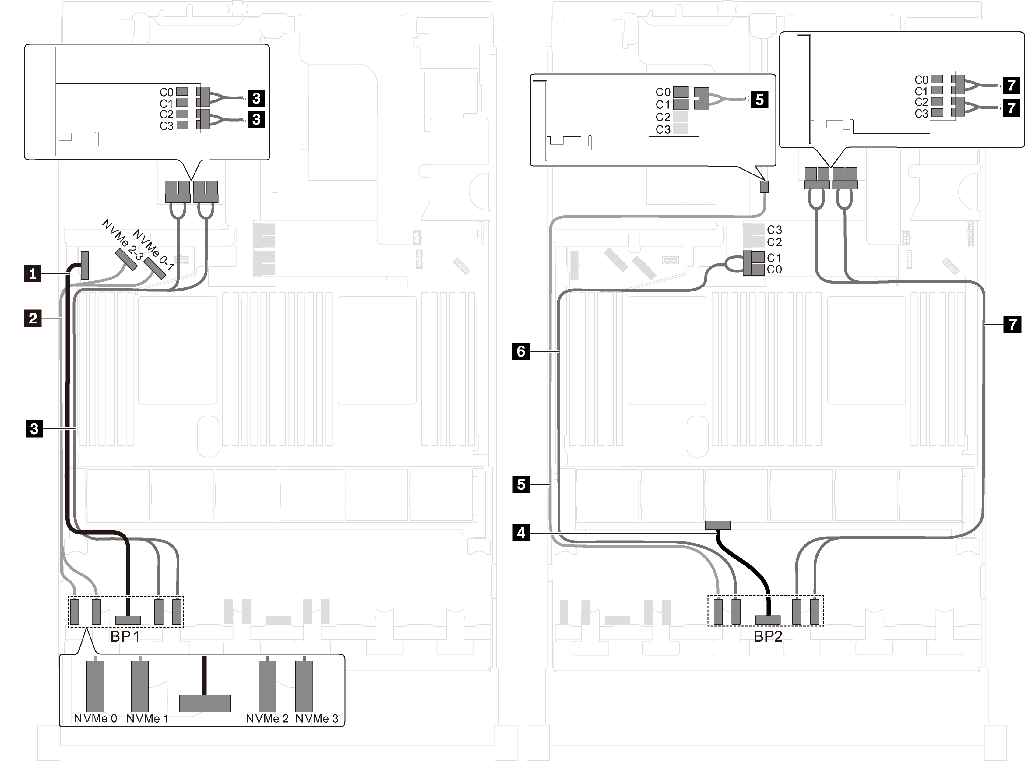
Server model: sixteen 2.5-inch NVMe drives, two NVMe 810-4P switch adapters, two NVMe 1610-4P switch adapters
| Cable | From | To |
|---|---|---|
| 1 Power cable for front backplane 1 | Power connector on front backplane 1 | Backplane power connector 1 on the system board |
| 2 NVMe signal cable for front backplane 1 | NVMe 0 and NVMe 1 connectors on front backplane 1 | NVMe 2–3 and NVMe 0–1 connectors on the system board |
| 3 NVMe signal cable for front backplane 1 | NVMe 2 and NVMe 3 connectors on front backplane 1 | C0, C1, C2, and C3 connectors on the NVMe 1610-4P switch adapter installed in PCIe slot 6 |
| 4 Power cable for front backplane 2 | Power connector on front backplane 2 | Backplane power connector 2 on the system board |
| 5 NVMe signal cable for front backplane 2 | NVMe 0 connector on front backplane 2 | C0 and C1 connector on the NVMe 810-4P switch adapter installed in PCIe slot 4 |
| 6 NVMe signal cable for front backplane 2 | NVMe 1 connector on front backplane 2 | C0 and C1 connector on the NVMe 810-4P switch adapter installed in RAID adapter slot on the system board |
| 7 NVMe signal cable for front backplane 2 | NVMe 2 and NVMe 3 connectors on front backplane 2 | C0, C1, C2, and C3 connectors on the NVMe 1610-4P switch adapter installed in PCIe slot 1 |
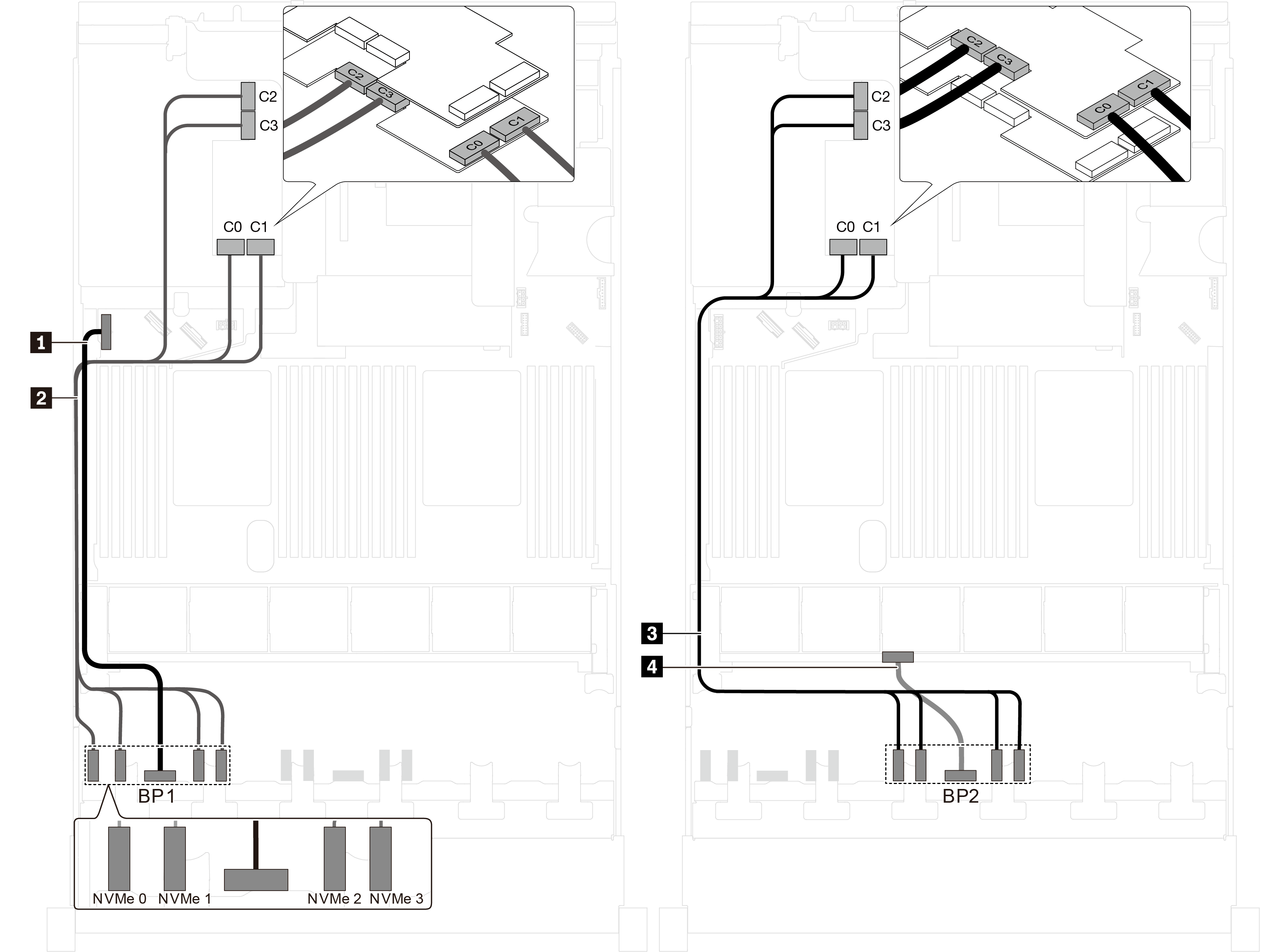
Server model: sixteen 2.5-inch NVMe drives, two NVMe 1611-8P switch adapters
| Cable | From | To |
|---|---|---|
| 1 Power cable for front backplane 1 | Power connector on front backplane 1 | Backplane power connector 1 on the system board |
| 2 NVMe signal cable for front backplane 1 | NVMe 0, NVMe 1, NVMe 2, and NVMe 3 connectors on front backplane 1 | C0, C1, C2, and C3 connectors on the NVMe 1611-8P switch adapter installed in PCIe slot 6 |
| 3 NVMe signal cable for front backplane 2 | NVMe 0, NVMe 1, NVMe 2, and NVMe 3 connectors on front backplane 2 | C0, C1, C2, and C3 connectors on the NVMe 1611-8P switch adapter installed in PCIe slot 5 |
| 4 Power cable for front backplane 2 | Power connector on front backplane 2 | Backplane power connector 2 on the system board |