System-board-assembly switch
This section provides information about locations and functions of the switch block on the system board assembly that contains the system I/O board and processor board.
Important
Before you change any switch settings or move any jumpers, turn off the server; then, disconnect all power cords and external cables. Review the following information:
- Any system-board-assembly switch or jumper block that is not shown in the illustrations in this document are reserved.
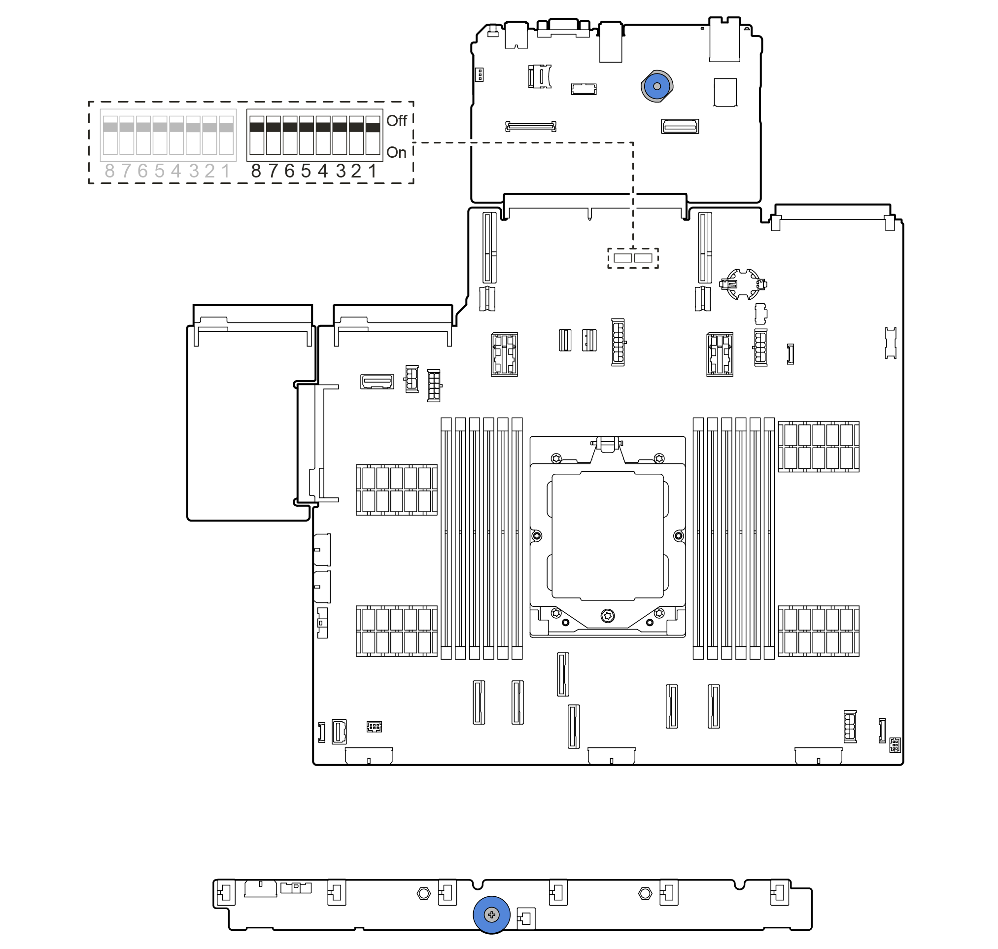
Figure 1. Switch block on the system board assembly
SW5 switch block
The following table describes the functions of the SW5 switch block on the system board assembly.
| Switch number | Switch name | Default position | Description |
|---|---|---|---|
| SW5-1 | Force BMC CPU reset | Off | Forces BMC and CPU into reset when changing it to the ON position. |
| SW5-2 | Clear CMOS | Off | Clears the real-time clock (RTC) registry when changing it to the ON position. |
| SW5-3 | Override power-on password | Off | Overrides the power-on password when changing it to the ON position. |
| SW5-4 | FPGA reset | Off | Forces FPGA into reset when changing it to the ON position. |
| SW5-5 | Reserved | Off | Reserved |
| SW5-6 | Reserved | Off | Reserved |
| SW5-7 | Reserved | Off | Reserved |
| SW5-8 | Reserved | Off | Reserved |
Give documentation feedback