Install the front I/O module
Follow instructions in this section to install the front I/O module.
About this task
Attention
Read Installation Guidelines and Safety inspection checklist to ensure that you work safely.
Touch the static-protective package that contains the component to any unpainted metal surface on the server; then, remove it from the package and place it on a static-protective surface.
Procedure
- Install the front I/O module.NoteIf the front I/O module slot is covered with a slot bracket, remove the bracket from the chassis first.
 Insert the front I/O module into the front I/O module slot. Ensure that the module is fully seated.
 Fasten the front I/O module retention screw.Figure 1. Installing the front I/O module
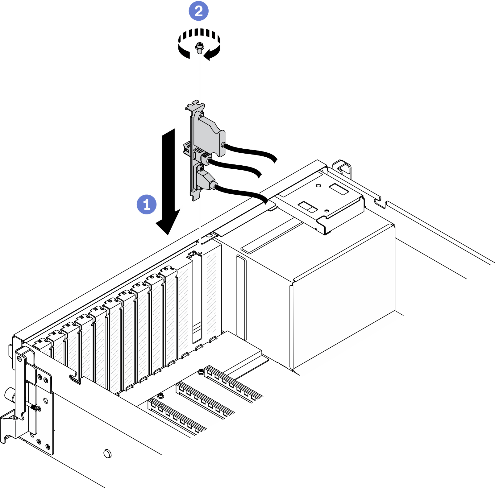
- Connect the front USB, video and external LCD diagnostics handset cables from the front I/O module to their respective connectors on the system board. Note
The front I/O module cabling is different by server model. Refer to the front I/O module cable routing guide for each server model below. See System-board connectors for more details.
From To Front I/O module 1 Video cable System board 1 Front VGA connector 2 External LCD diagnostics handset cables 2 LCD connector 3 USB cable 3 Front USB connector Figure 2. 4-DW GPU Model front I/O module cable routing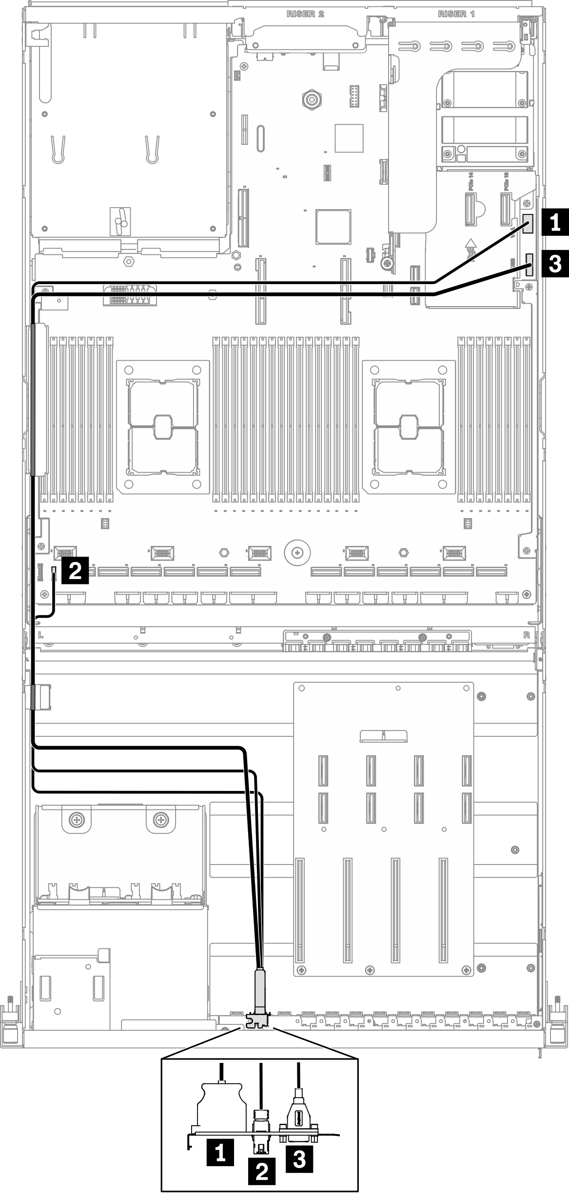 Figure 3. 8-DW GPU Model front I/O module cable routing
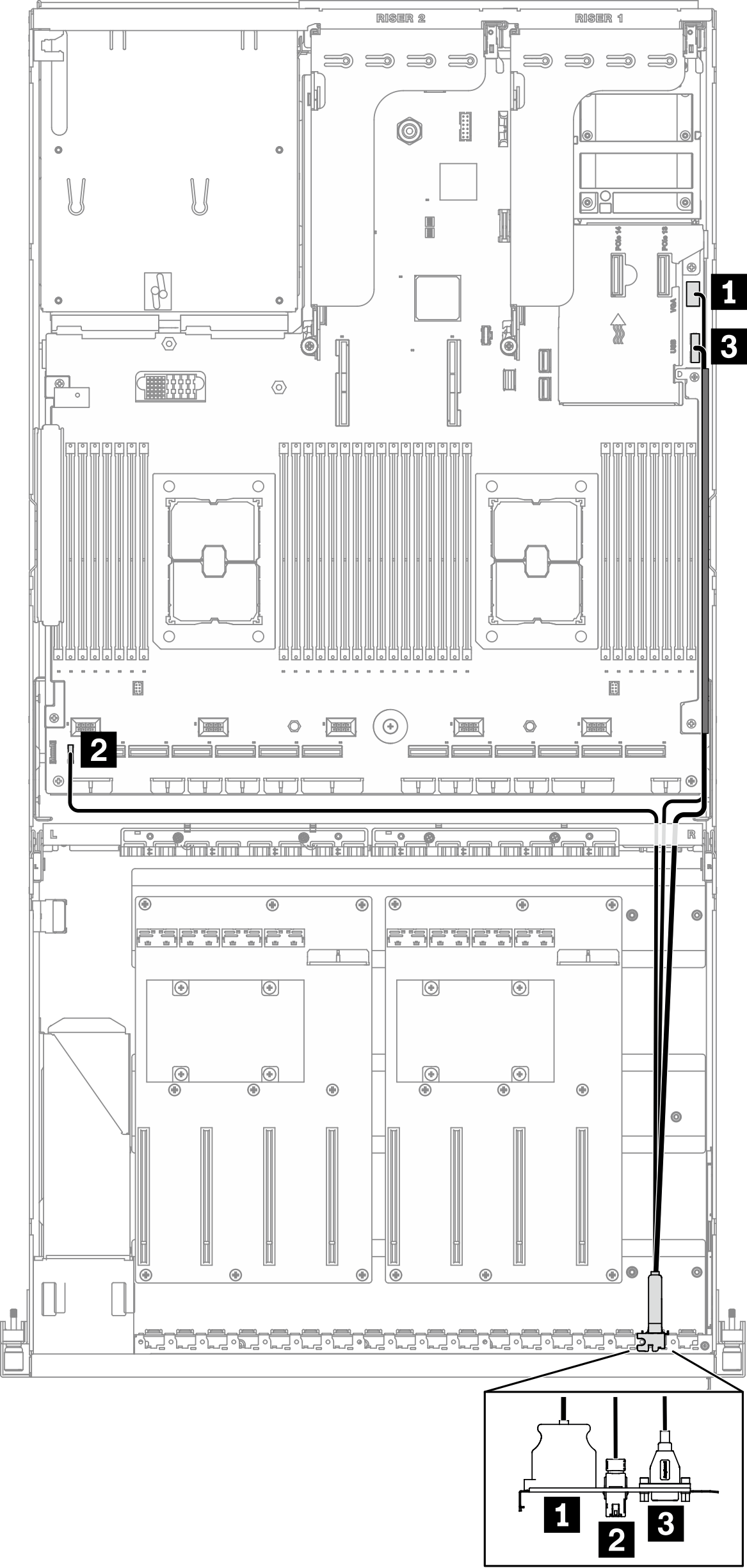 Figure 4. SXM GPU Model front I/O module cable routing
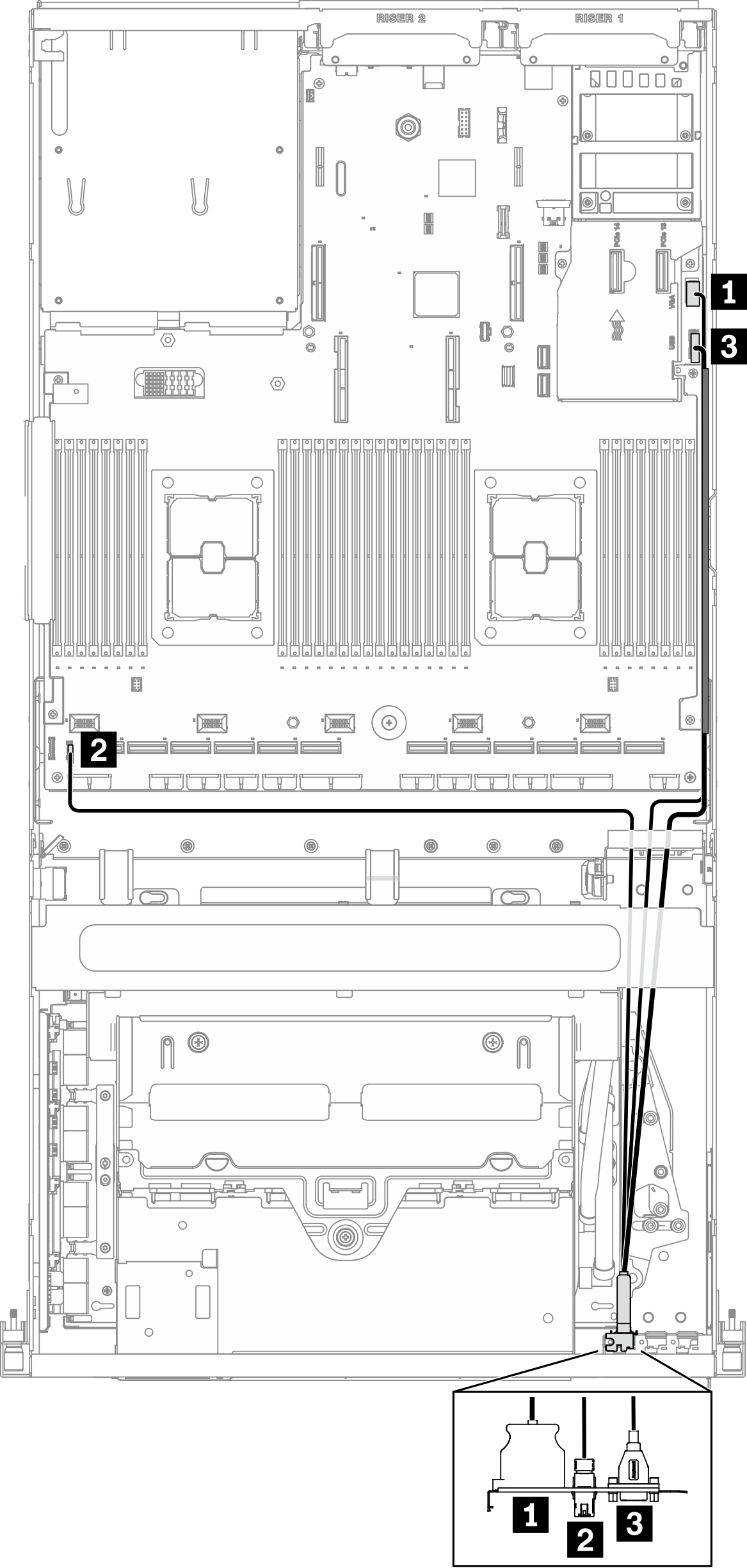
Give documentation feedback