Install the system board
Use this information to install the system board.


Before installing the system board, touch the static-protective package that contains the new system board to any unpainted surface on the outside of the server. Then, take the new system board out of the package and place it on a static-protective surface.
To install the system board, complete the following steps:
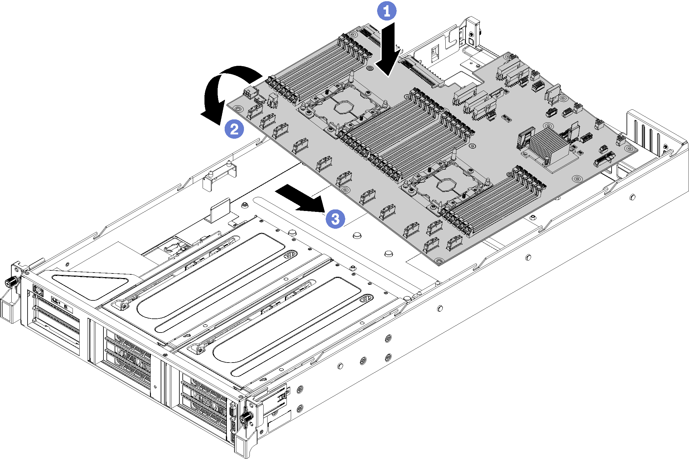
- Carefully, lower the right edge of the system board (as you are looking at the front of the server) onto the chassis.
- Rotate the left edge of the system board onto the chassis.
- Slide the system board into place.
- Install the 10 screws.
- Install the two M.2 adapter guideposts. Use the 6mm nut drive tool (hex socket) that was provided with the system board replacement to install the adapter guideposts.
- Install the two air baffle posts.
After installing the system board:
Route the cables for the PCIe expansion cages and the I/O expansion cage from the front of the server to the rear of the server through the cable caps and cable guides to connect them to the system board.
- Install any components that you removed from the failing system board.
DIMMs
M.2 backplane
TPM card (for Chinese Mainland only)
CMOS battery
PHM
Install the drive cage. See Install the drive cage.
Install the system fan cage. See Install the system fan cage.
Install the air baffle. See Install the air baffle.
Install the top cover. See Install the top cover.
Push up on the latches on the slide rails and push the server back into the rack.
Tighten the two captive screws located on the front of the server to secure the server in the rack.
NoteAlways secure the system in the rack if your are moving the rack.Connect all cables to the ports on the front of the server, including the management port, if necessary, and all PCIe adapter ports. The management port and PCIe adapter ports are located in the I/O expansion cage.
Re-engage both power supplies.
Connect power cords to both power supplies, which are located at the rear of the server.
Power on the server.
Update the machine type and serial number with new vital product data (VPD). Use the Lenovo XClarity Provisioning Manager to update the machine type and serial number. See Update the machine type and serial number.
Enable TPM/TCM. See Enable TPM.
Optionally, enable UEFI Secure Boot. See Enable UEFI Secure Boot.
Demo video