x16 OCP module
Use the section to understand the cable routing for the x16 OCP module.
Choose the routing plan according to the number of drive installed in the system:
No drive — configurations 10 and 16
Figure 1. OCP module cable routing
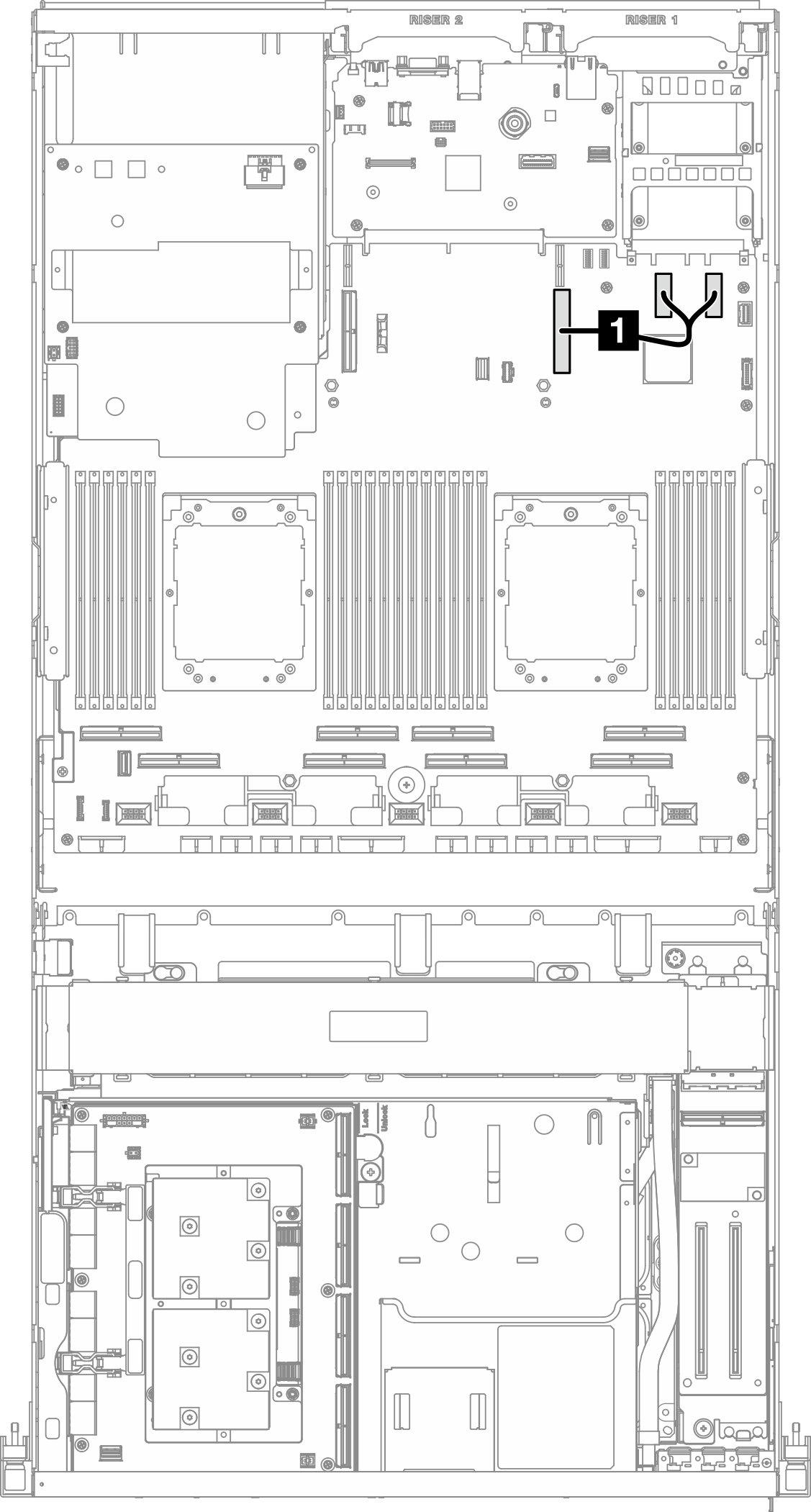
| Cable | From | To |
|---|---|---|
| 1 | System board assembly: PCIe connectors 11 and 12 | System board assembly: PCIe connector 9 |
Four 2.5-inch/E3.S drives — configurations 7, 8, 12, 18, 25, 26, 28, and 31
Figure 2. OCP module cable routing
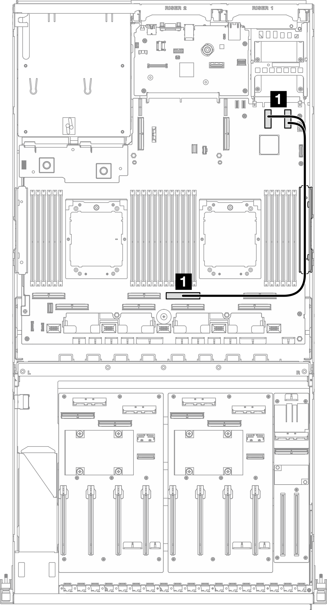
| Cable | From | To |
|---|---|---|
| 1 | System board assembly: PCIe connectors 11 and 12 | System board assembly: PCIe connector 4 |
Give documentation feedback