ダイレクト GPU 分電盤の構成
このセクションでは、ダイレクト GPU 分電盤のサーバー構成向け OCP モジュール・ケーブル配線について説明します。
システムに、前面 I/O 拡張ボードが取り付けられているかどうかに応じて、配線計画を選択します。
前面 I/O 拡張ボードなし — 構成 36 および 37
図 1. OCP モジュールのケーブル配線
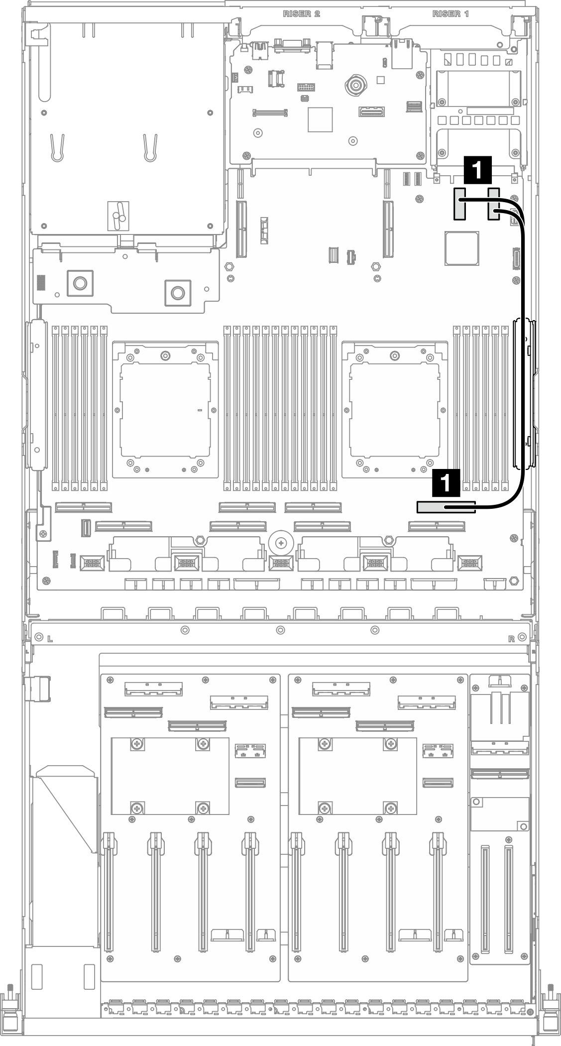
| ケーブル | 始点 | 終点 |
|---|---|---|
| 1 | システム・ボード・アセンブリー: PCIe コネクター 11 および 12 | システム・ボード・アセンブリー: PCIe コネクター 2 |
前面 I/O 拡張ボードあり — 構成 3 および 22
図 2. OCP モジュールのケーブル配線
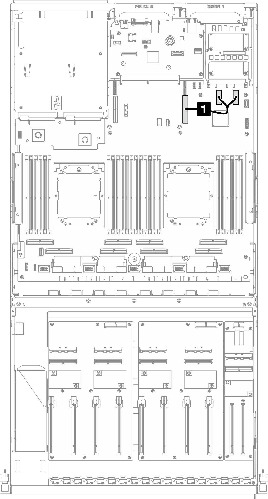
| ケーブル | 始点 | 終点 |
|---|---|---|
| 1 | システム・ボード・アセンブリー: PCIe コネクター 11 および 12 | システム・ボード・アセンブリー: PCIe コネクター 9 |
フィードバックを送る