Front I/O module and integrated diagnostics panel cable routing
Use the section to understand the cable routing for the front I/O module and the integrated diagnostics panel.
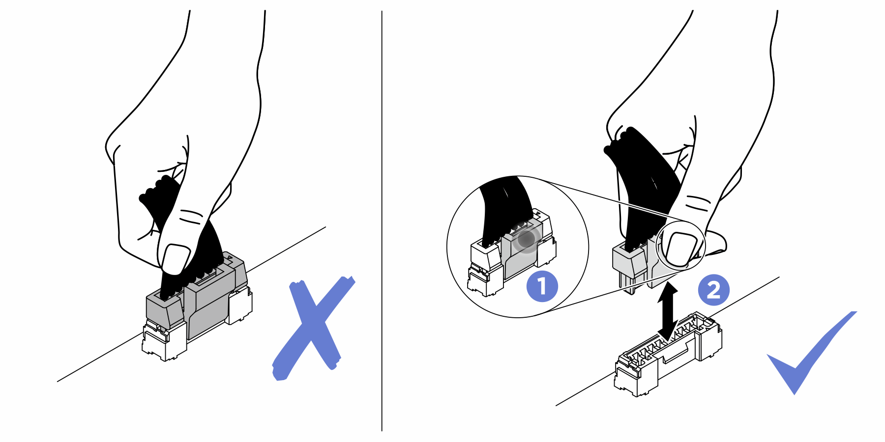
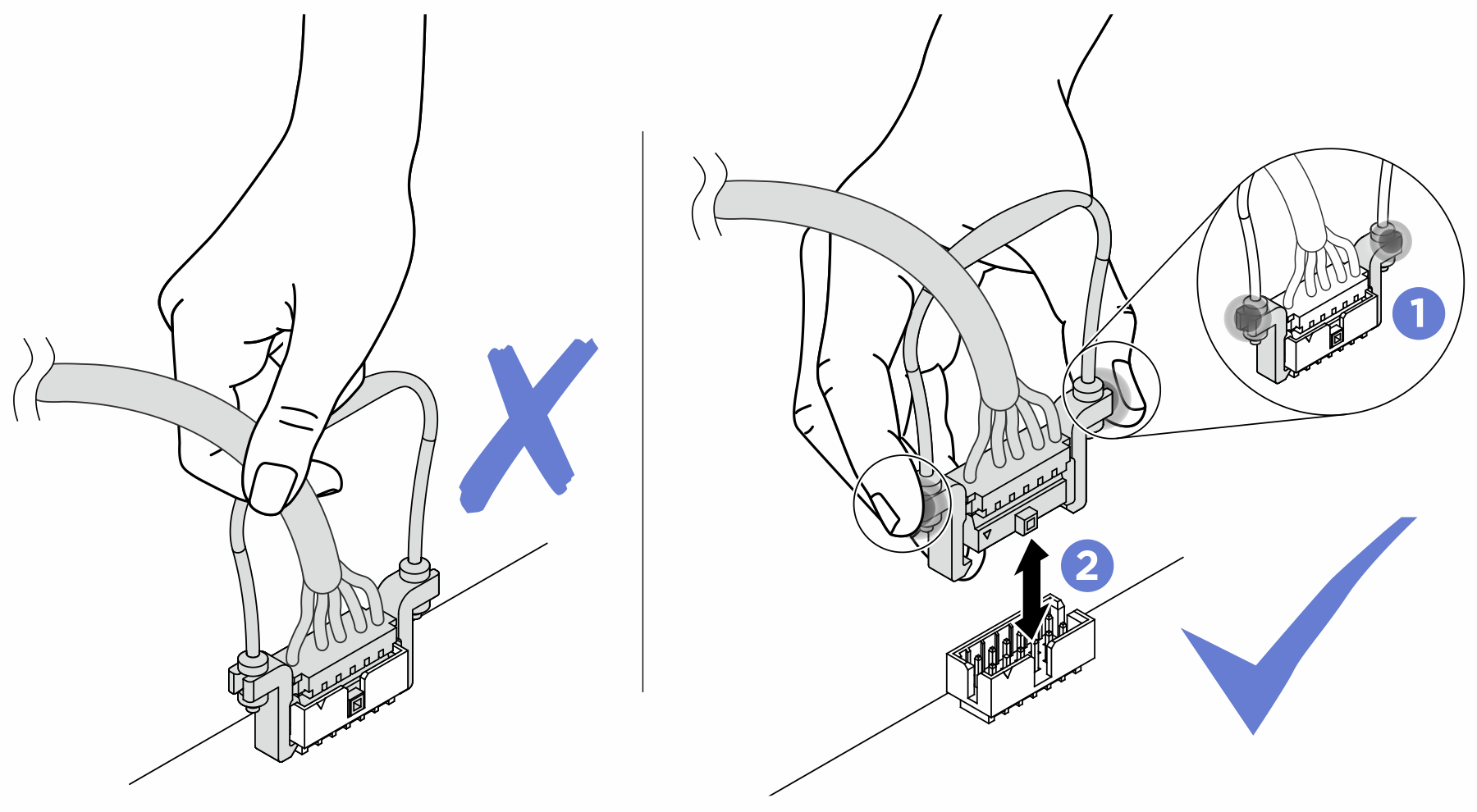
Attention
Strictly observe the following instructions to avoid damaging cable sockets on the system board. Any damage to the cable sockets might require replacing the system board.
Connect cable connectors vertically or horizontally in alignment with the orientations of the corresponding cable sockets, avoiding any tilt.
- To disconnect cables from the system board, do as follows:
Press and hold all latches, release tabs, or locks on cable connectors to release the cable connectors.
- Remove the cable connectors vertically or horizontally in alignment with the orientations of the corresponding cable sockets, avoiding any tilt.NoteThe cable connectors might look different from those in the illustration, but the removal procedure is the same.

Based on the location, select the corresponding routing plan:
After you finish cable routing, bundle the cables with cable ties corresponding to their location:
Note
- Connections between connectors; 1↔1, 2↔2, 3↔3, ... n↔n
- When routing the cables, ensure that all cables are routed appropriately through the cable guides.
Front I/O module cable routing
Figure 1. Front I/O module cable routing
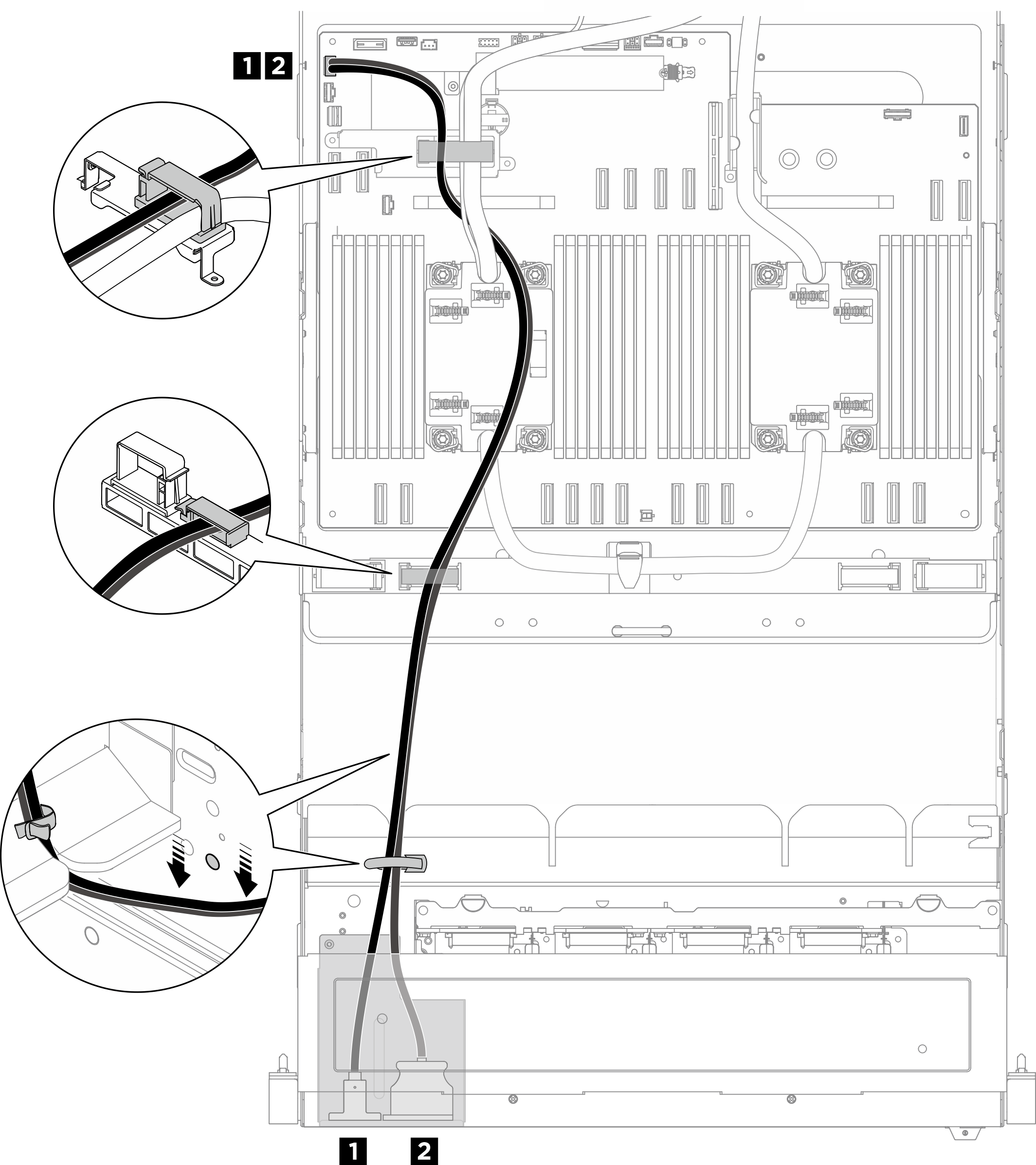
| Cable | From | To | Label |
|---|---|---|---|
| 1 | Front I/O module: Mini DisplayPort cable | System board assembly: Front USB / Mini DisplayPort connector (FRONT IO1) |
|
| 2 | Front I/O module: USB cable |
Integrated diagnostics panel cable routing
Figure 2. Integrated diagnostics panel cable routing
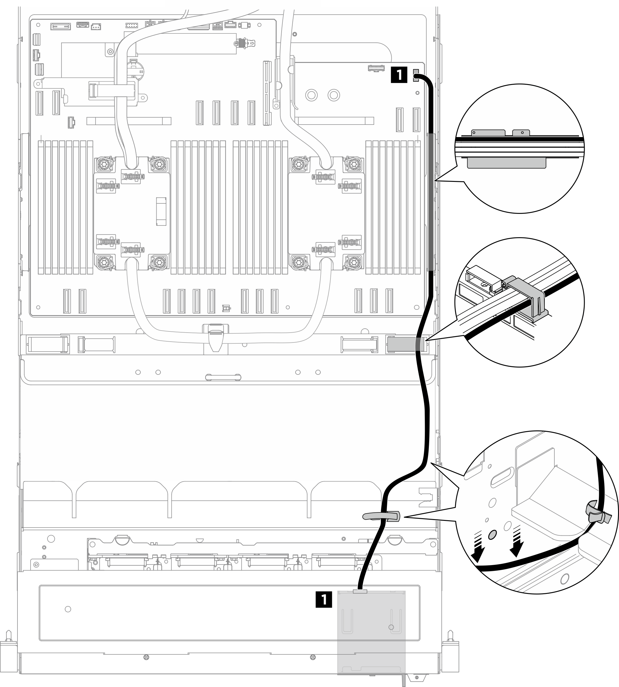
| Cable | From | To | Label |
|---|---|---|---|
| 1 | Integrated diagnostics panel: Integrated diagnostics panel cable | System board assembly: Integrated diagnostics panel connector (FRONT IO2) |
|
Note
- Ensure to keep the integrated diagnostics panel cable and the front I/O module cable lower than the circle mark on the chassis as illustrated.
- When routing through the cable guides on the CPU complex chassis, keep the integrated diagnostics panel cable on top of the power cables, and keep them parallel to each other.
After you finish
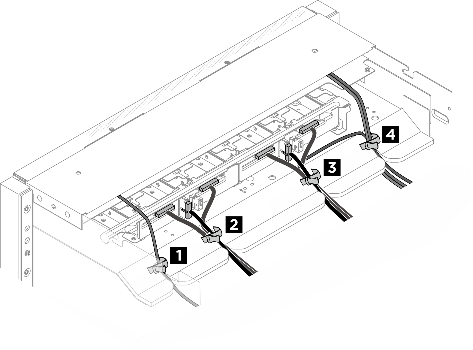
Figure 3. Securing cables with cable ties
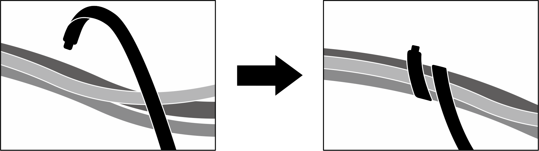
Bundle cables on the front drive backplane side
Divide the drive backplane signal and power cables, GPU management cable, front I/O module cables, and integrated diagnostics panel cable into four bundles, and secure them with cable ties as illustrated.
| Bundle | Cable | Connector |
| 1 |
|
|
| 2 |
|
|
| 3 |
|
|
| 4 |
|
|
Give documentation feedback